Coated high pressure gasoline injector seat to reduce particle emissions

a high-pressure gasoline and particle emission technology, applied in the direction of fuel injection apparatus, machine/engine, feed system, etc., can solve the problems of increasing the risk of deposits being formed in the metering passage itself, imposing similarly challenging standards,

Active Publication Date: 2017-12-19
VITESCO TECH USA LLC
View PDF16 Cites 0 Cited by
  • Summary
  • Abstract
  • Description
  • Claims
  • Application Information

AI Technical Summary

Benefits of technology

[0006]An object of the invention is to fulfill the need referred to above. In accordance with the principles of the embodiments, this objective is obtained by providing a fuel injector having an inlet, an outlet, and a passageway providing a fuel flow conduit from the inlet to the outlet. The fuel injector includes a valve structure movable in the passageway between a first position and a second position. A seat, at the outlet, has at least one seat passage in communication with the passageway. The seat contiguously engages a portion of the valve structure in the first position thereby closing the at least one seat passage and preventing fuel from exiting the at least one passage. The valve structure in the second position is spaced from the at least one seat passage so that fuel can move through the passageway and exit through the at least one

Problems solved by technology

Similarly, United States regulations will impose similarly challenging standards with the introduct

Method used


Image

  • Coated high pressure gasoline injector seat to reduce particle emissions
  • Coated high pressure gasoline injector seat to reduce particle emissions
  • Coated high pressure gasoline injector seat to reduce particle emissions

Examples


Embodiment Construction

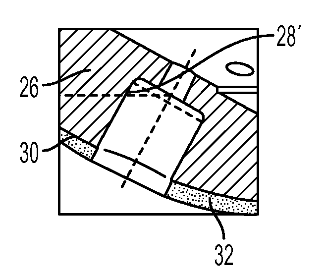
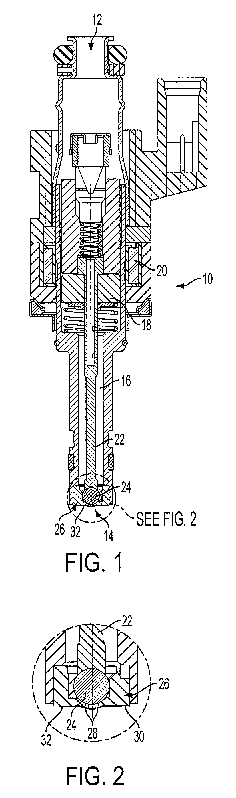
[0015]With reference to FIG. 1, a gasoline direct fuel injector is shown, generally indicated at 10, in accordance with an embodiment of the invention. The fuel injector 10 has a fuel inlet 12, a fuel outlet 14, and a fuel passageway 16 extending from the fuel inlet 12 to the fuel outlet 14. The injector 10 is of the conventional, solenoid-operated type, having an armature 18 operated by a coil 20. Electromagnetic force is generated by current flow from the electronic control unit (not shown) through the coil 20. Movement of the armature 18 also moves an operatively attached needle 22 and ball valve 24 to positions that are either separated from or contiguously engaged with a seat, generally indicated at 26. The needle 22 and ball valve 24 define valve structure of the injector 10. Instead of providing the ball valve 24, it can be appreciated that the valve structure could only comprise the needle 22, with an end of the needle engaging the seat 26.

[0016]Movement of the ball valve 24...


PUM


Abstract

A fuel injector has a seat and at least one seat passage. The seat includes an outer tip surface through which the seat passage extends. A non-thermally conducting coating is provided on at least a portion of the outer tip surface and not on surfaces defining the seat passage. The coating is constructed and arranged to be heated by combustion gases so that the outer tip surface reaches a temperature greater than a temperature that the outer tip surface would reach if the coating was not provided so as to cause evaporation of fuel that contacts the outer tip surface, The seat passage is constructed and arranged to not be substantially heated by conduction from the outer tip surface and to be cooled by fuel passing there-through so as to prevent deposits of combustion from accumulating on surfaces defining the seat passage.

Description

FIELD[0001]The invention relates to gasoline direct injection for vehicles and, more particularly, to providing a non-thermally conducting coating on a fuel injector tip to increase a temperature thereof and thus reduce particulate emissions.BACKGROUND[0002]Particulate emissions of gasoline engines will be newly regulated in Europe in 2014 with the introduction of EU6a regulations of 6×10¹² particles / km and further reduced to 6×10¹¹ particles / km with the introduction of EU6c in 2017. Similarly, United States regulations will impose similarly challenging standards with the introduction of LEVIII. Standards are assumed to be 10 mg / mi in 2014, 3 mg / mi in 2018 and 1 mg / mi in 2025. A major source of particulate emissions is known to be from a diffusion flame fed by fuel evaporating from the deposits on the fuel injector tip.[0003]It is known that protruding the fuel injector further into the combustion chamber reduces the particulate emissions. Increasing injector tip protrusion raises i...

Claims


Application Information

Patent Timeline
IPC IPC(8): F02M53/04F02M61/18F02M51/06F02M61/16
CPCF02M53/046F02M51/0685F02M61/166F02M61/1886F02M61/1833F02M2200/9038F02M2200/06
Inventor IMOEHL, WILLIAM JAMESZHANG, HONG
Owner VITESCO TECH USA LLC
Why Eureka
Try Eureka