Supercharge Your Innovation With Domain-Expert AI Agents!

Safety lock for cam lock fitting

a safety lock and cam lock technology, applied in the direction of pipe couplings, pipes, pipes, etc., can solve the problems of injuring the operator or unwelcome release of materials to the environment, and achieve the effect of preventing inadvertent pressure discharg

Active Publication Date: 2022-05-03
HARTMAN JEFFREY +1
View PDF13 Cites 0 Cited by
  • Summary
  • Abstract
  • Description
  • Claims
  • Application Information

AI Technical Summary

Benefits of technology

Prevents accidental discharge of pressurized materials by allowing the operator to assess pressure status before fully opening the fitting, ensuring safety and preventing environmental damage.

Problems solved by technology

A major problem sought to be solved by the present invention is that which occurs when an operator of a conventional cam lock fitting undertakes the operation of opening a conventional cam lock fitting and the operator may not know if the contents of the conventional fitting are still under pressure, and if the contents are still under pressure the contents will spew out when the conventional fitting is opened possibly resulting in injury to the operator or an unwanted release of materials to the environment.

Method used


Image

  • Safety lock for cam lock fitting
  • Safety lock for cam lock fitting
  • Safety lock for cam lock fitting

Examples


embodiment 11

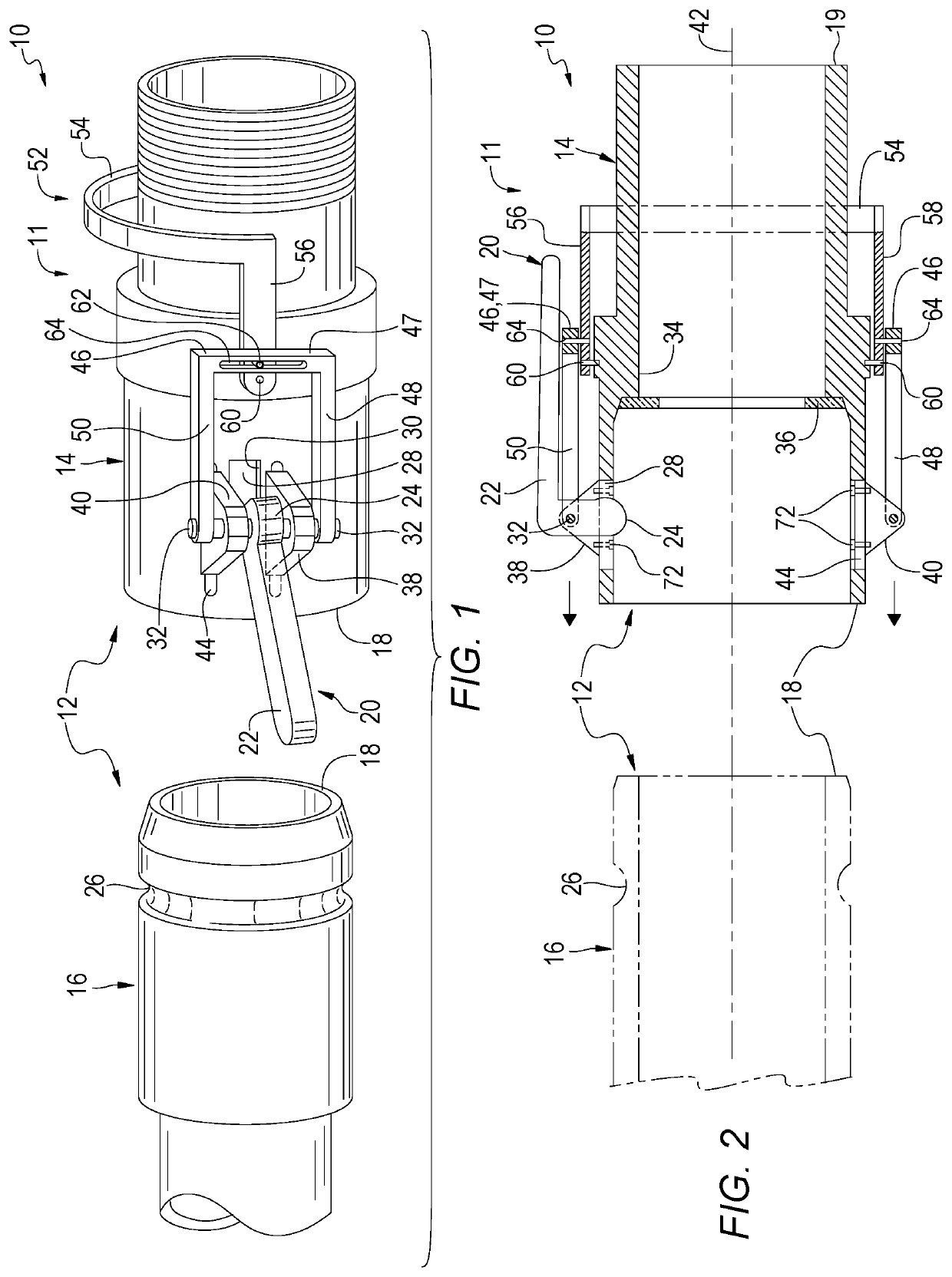
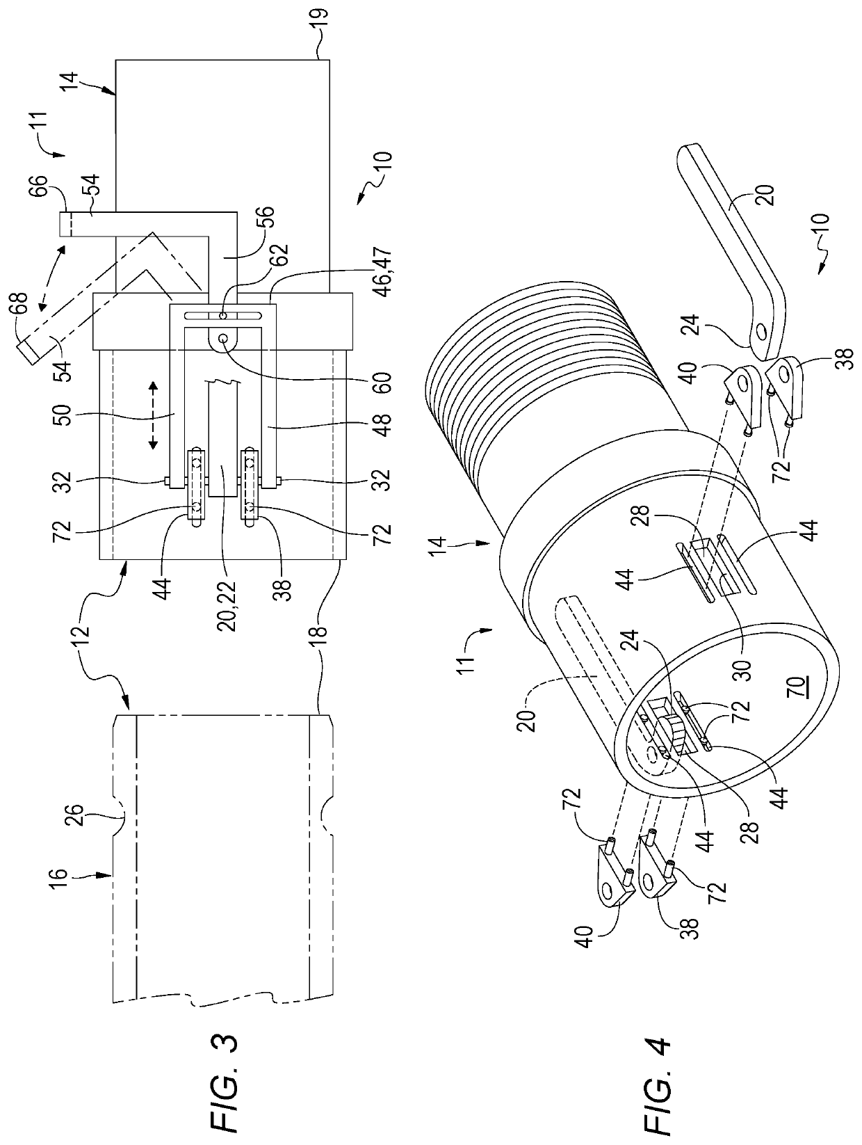
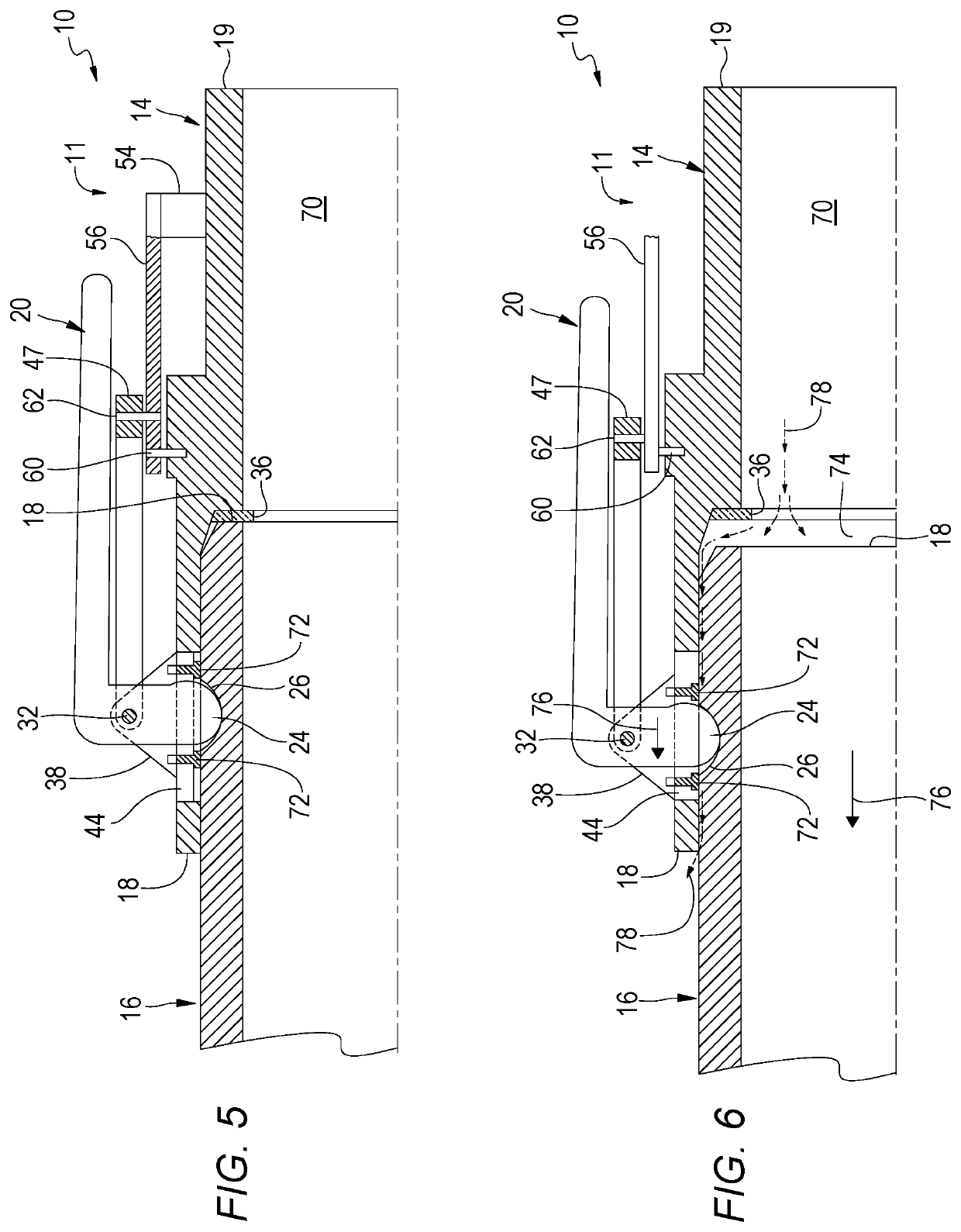
[0076]By way of additional general explanation, and by making reference to FIGS. 1-6, embodiment 11 of the present invention 10 discloses a safety lock mechanism 52 mounted on an outside surface of female coupling 14 proximate the cam member or lever 20 wherein the safety lock mechanism has a handle 54 which moves a bracket 46 connected to bosses 38, 40 so that when fluid in the cam lock fitting 12 is pressurized the handle remains in a first position 66 so as to seal and lock the cam lock fitting 12. In order to open the cam lock fitting 12, an operator must first move the handle 54 from the closed position 66 to open position 68 so as to allow the male coupling 16 end 18 to move slightly away from the O-ring 36 of female coupling 14 thereby creating a small space 74 to allow the operator to determine by visual or auditory observation, e.g., hissing, whether the cam lock fitting is pressurized or unpressurized. If the cam lock fitting 12 remains pressurized, the operator can quickl...

embodiment 13

[0079]In order for an operator to open a cam lock fitting 12 designed according to the teachings of embodiment 13 of the present invention 10, the operator must first move the safety handle 54 from the first downward closed position 66 to an intermediate position or partially open position 67 (as best seen in FIG. 9) so that the cam disks 80 are moved from a rearward position away from front end 18 to a more forward position toward front end 18 so as to relieve internal pressure contained inside the cam lock fitting so that when there is no pressure remaining in the cam lock fitting 12 the operator can continue with the next step of opening the cam lock fitting by pressing the head / catch 84 inwardly to allow handle 54 to be moved to the open position 68 for completely separating the male 16 and female 14 conduit portions. If there is still pressure inside the cam lock fitting 12 when the safety lock handle 54 is opened, the operator will immediately reclose the safety lock handle 54...


PUM


Abstract

Method and apparatus for a safety lock assembly for a cam lock fitting mounted onto the outside of the cam lock fitting in close proximity to the cam levers to prevent complete separation of the male and the female portions of the fitting to prevent inadvertent pressurized discharge of dangerous materials. In one embodiment, this is accomplished by having slidable bosses upon which the cam levers are mounted which bosses are adapted to slide in response to movement of a safety handle so that the male and female portions of the cam lock fitting only slightly separate from each other allowing the operator to quickly reclose the cam lock fitting if the operator observes that the cam lock fitting still contains pressurized material. In a second embodiment, an earless cam disk moves on slotted, fixedly mounted bosses in response to movement of a safety handle similarly to the first embodiment.

Description

RELATED APPLICATIONS[0001]This application is a divisional application of U.S. patent application Ser. No. 15 / 416,002 filed Jan. 26, 2017 now patent Ser. No. 10 / 655,769.BACKGROUND OF INVENTIONField of the Invention[0002]The present invention relates generally to cam lock fittings and, more particularly, is concerned with a safety lock for a cam lock fitting.Description of the Prior Art[0003]Cam lock fittings having safety features have been described in the related art. However, none of the related art devices disclose the unique features of the present invention. U.S. Pat. No. 6,095,190 to Wilcox, et al., dated Aug. 1, 2000, disclosed a coupling with a female half having internal pressure relief. U.S. Pat. No. 5,863,079 to Donais, et. al., dated Jan. 26, 1999, disclosed a quick-connect, disconnect coupling. U.S. Pat. No. 5,595,217 to Gillen, et al., dated Jan. 21, 1997, disclosed a dry break coupling assembly with a cam locking connection system, U.S. Pat. No. 5,234,017 to Aflin, e...

Claims


Application Information

Patent Timeline
Patent Type & Authority Patents(United States)
IPC IPC(8): F16L37/18
CPCF16L37/18F16L2201/30Y10T29/49826
Inventor HARTMAN, JEFFREYWILLIAMSON, GEORGE L
Owner HARTMAN JEFFREY
Features
  • R&D
  • Intellectual Property
  • Life Sciences
  • Materials
  • Tech Scout
  • Unparalleled Data Quality
  • Higher Quality Content
  • 60% Fewer Hallucinations
Learn More