Air conditioning with recovery wheel, dehumidification wheel, and cooling coil
What is AI technical title?
AI technical title is built by Patsnap AI team. It summarizes the technical point description of the patent document.
a cooling coil and recovery wheel technology, applied in space heating and ventilation control systems, lighting and heating apparatuses, heating types, etc., can solve the problems of limiting the amount of cooling that can be provided, reducing the cooling effect of the cooling coil, and consuming energy
Active Publication Date: 2022-05-03
SEMCO INC
View PDF39 Cites 3 Cited by
Summary
Abstract
Description
Claims
Application Information
AI Technical Summary
This helps you quickly interpret patents by identifying the three key elements:
Problems solved by technology
Method used
Benefits of technology
Benefits of technology
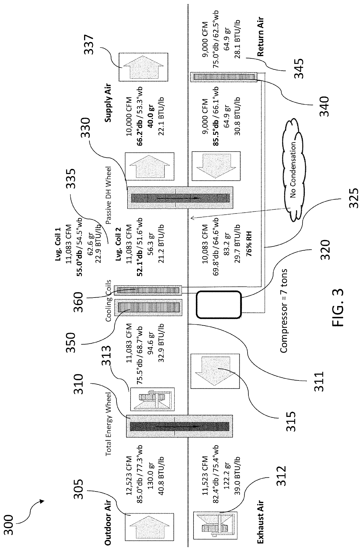
[0010]Even further, some embodiments provide dryer supply air than certain prior art alternatives (e.g., for compatibility with chilled beams), provide less risk of condensation or better cooling performance of the chilled beams (e.g., due to a lower dew point within the space), or a combination thereof. Certain embodiments provide, for example, as objects or benefits, for instance, that they improve the performance of active chilled beam system designs. Different embodiments simplify the design and installation of chilled beam systems, reduce the installed cost of the technology, increase energy efficiency, or a combination thereof, as examples. In addition, various other embodiments of the invention are also described herein, and other benefits of certain embodiments may be apparent to a person of ordinary skill in the art.
Problems solved by technology
But adding or removing heat or humidity (moisture) typically involves the expenditure of energy.
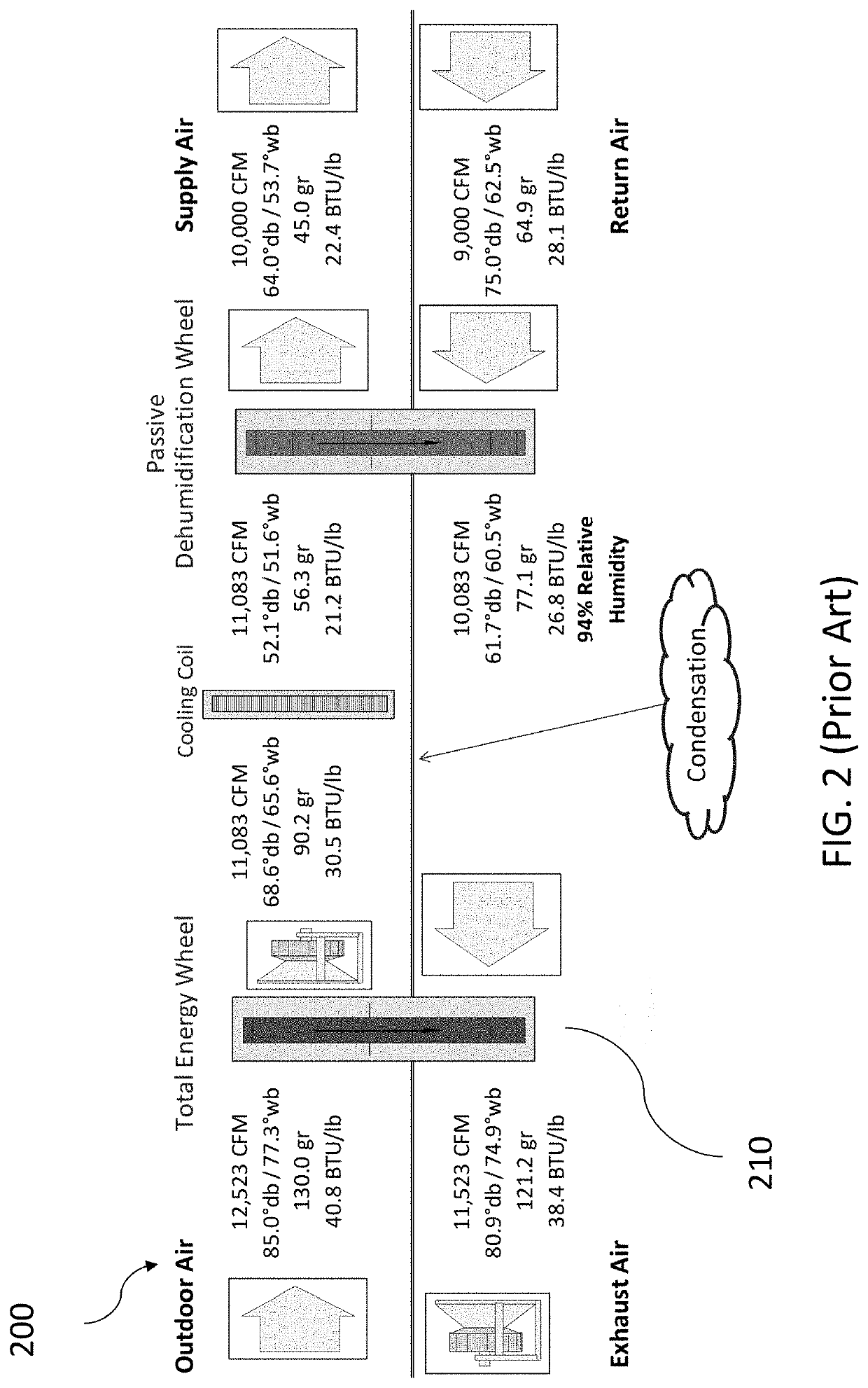
Further still, in chilled beam applications, humidity levels in the room air can limit the amount of cooling that can be provided through the chilled beams because the chilled beams cannot be cooled below the room air dew point or else condensation will occur on the chilled beams which will drip on the occupants and other contents of the space.
In chilled water systems, however, the minimum temperature that the air leaving the cooling coil can reach has been limited by how cold the chilled water can be produced using traditional chiller performance limitations.
As a result, the amount of humidity that can be removed from the outdoor air, for example, is limited.
Moreover, in prior art systems, when supply air was cooled in the cooling coil sufficiently to provide the desired level of supply air humidity, supply air temperatures were often colder than desired.
Method used
Image
Click on the blue label to locate the original text in one second.
Reading with bidirectional positioning of images and text.
Examples
Embodiment Construction
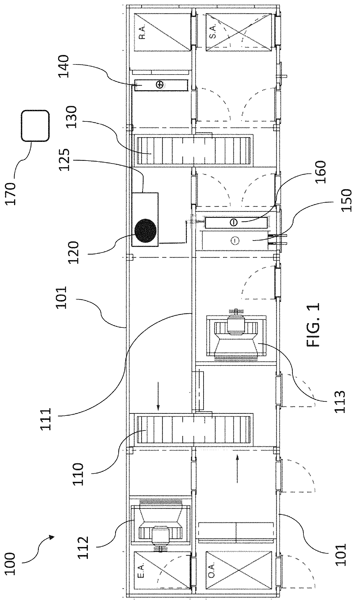
[0008]This invention provides, among other things, various air conditioning units, systems, and methods that control temperature and humidity, for instance, within a space in a building. Various units and systems, for example, include a recovery wheel, a (e.g., passive) dehumidification wheel, a primary cooling coil, a secondary cooling coil, and a heating coil. Further, in various embodiments, a supply airstream passes outdoor air first through the recovery wheel, then through the primary cooling coil, then through the secondary cooling coil, then through the dehumidification wheel, and then to the space. Still further, in many embodiments, an exhaust airstream passes return air from the space first through the heating coil, then through the dehumidification wheel, and then through the recovery wheel.
[0009]Various embodiments provide, for example, as an object or benefit, that they partially or fully address or satisfy one or more of the needs, potential areas for benefit, or oppor...
PUM
Abstract
Methods and systems for controlling temperature and humidity within a space in a building. Outdoor air and return air from the space are passed through particular equipment in a particular order. Equipment includes a secondary direct-expansion refrigeration circuit, a recovery wheel, a primary cooling coil or direct-expansion refrigeration circuit, secondary circuit coils, and a dehumidification wheel. Various embodiments include modulating the secondary circuit compressor to adjust reheat capacity at the secondary circuit condenser coil, a geothermal direct-expansion refrigeration circuit, a variable refrigerant flow subsystem, fan coil units, multiple zones, a dedicated outdoor air supply subsystem, an evaporative cooler, supplemental outdoor air, or a combination thereof. In some embodiments, supply air passes first through the recovery wheel, then through the primary cooling coil, then through the dehumidification wheel, and then to the space. Further, in some embodiments, exhaust air passes through the dehumidification wheel, and then through the recovery wheel.
Description
RELATED PATENT APPLICATIONS[0001]This United States patent application is a non-provisional patent application of, and claims priority to, U.S. Provisional patent application Ser. No. 62 / 779,356, filed on Dec. 13, 2018, titled: AIR CONDITIONING IMPROVEMENTS. This patent application is also a continuation-in-part (CIP) patent application of, and claims priority to, U.S. patent application Ser. No. 15 / 616,702, filed Jun. 7, 2017, titled: AIR CONDITIONING WITH RECOVERY WHEEL, PASSIVE DEHUMIDIFICATION WHEEL, COOLING COIL, AND SECONDARY DIRECT-EXPANSION CIRCUIT, which is a non-provisional patent application of, and claims priority to U.S. provisional patent application Ser. No. 62 / 347,517, filed on Jun. 8, 2016, also titled: AIR CONDITIONING WITH RECOVERY WHEEL, PASSIVE DEHUMIDIFICATION WHEEL, COOLING COIL, AND SECONDARY DIRECT-EXPANSION CIRCUIT. This patent application and these priority patent applications all have the same inventor and assignee listed above. In addition, the contents ...
Claims
Application Information
Patent Timeline
Application Date:The date an application was filed.
Publication Date:The date a patent or application was officially published.
First Publication Date:The earliest publication date of a patent with the same application number.
Issue Date:Publication date of the patent grant document.
PCT Entry Date:The Entry date of PCT National Phase.
Estimated Expiry Date:The statutory expiry date of a patent right according to the Patent Law, and it is the longest term of protection that the patent right can achieve without the termination of the patent right due to other reasons(Term extension factor has been taken into account ).
Invalid Date:Actual expiry date is based on effective date or publication date of legal transaction data of invalid patent.

