Image forming system, transport control method, and program

a technology of image forming and transport control, applied in the field of image forming system, transport control method, and program, can solve the problems of affecting the quality of the recording medium, the inability to use a single image forming apparatus, and the damage of paper as a recording medium, so as to prevent damage to the recording medium at low cost

Active Publication Date: 2022-05-03
KONICA MINOLTA INC
View PDF4 Cites 0 Cited by
  • Summary
  • Abstract
  • Description
  • Claims
  • Application Information

AI Technical Summary

Benefits of technology

[0011]It is an object of the present invention to provide an image forming system, a transport control method, and a program capable of preventing, at low cost, damage from occurring to a recording medium when printing is performed by two upstream and downstream image forming apparatuses.

Problems solved by technology

However, a conventional tandem machine as in JP 2012-203870 A can cause a problem that cannot happen in a single image forming apparatus.
Specifically, there is a problem that damage such as wrinkles or large curl is likely to occur to paper as a recording medium because the paper passes through a fuser of an upstream machine and a fuser of a downstream machine with its position, that is, the front and back sides and the front and rear edges in a transport direction unchanged.
On the other hand, if large curl occurs in paper, not only the quality deteriorates but also a jam is likely to occur before the paper is ejected to the outside of the machine.
The risk of such damage is typically greater when a recording medium is thin paper.
However, this leads to an increase in the size of the entire system and an increase in cost.

Method used


Image

  • Image forming system, transport control method, and program
  • Image forming system, transport control method, and program
  • Image forming system, transport control method, and program

Examples


Embodiment Construction

[0028]Hereinafter, one or more embodiments of the present invention will be described with reference to the drawings. However, the scope of the invention is not limited to the disclosed embodiments.

[0029][Overall Configuration of Image Forming System 10]

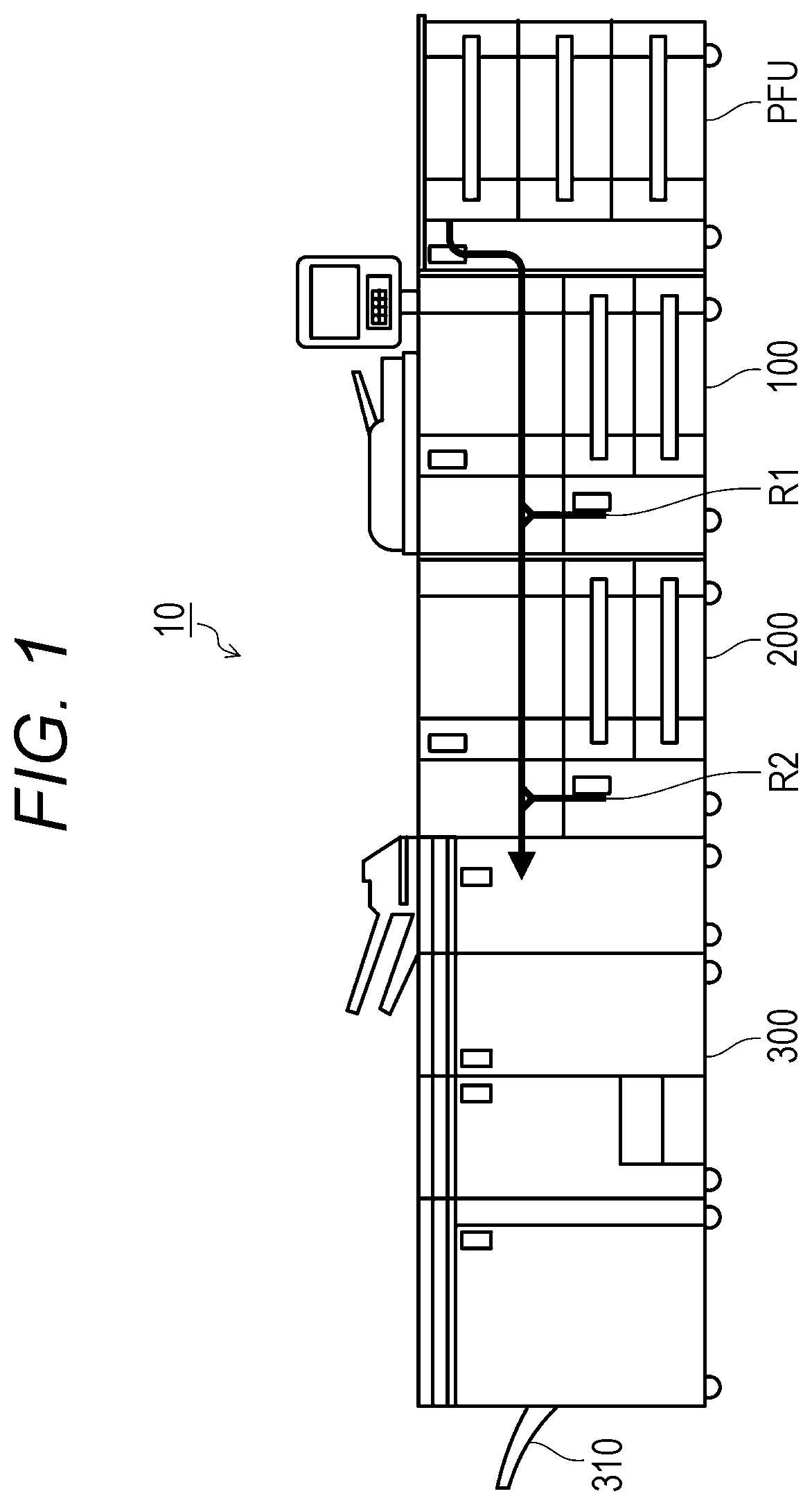
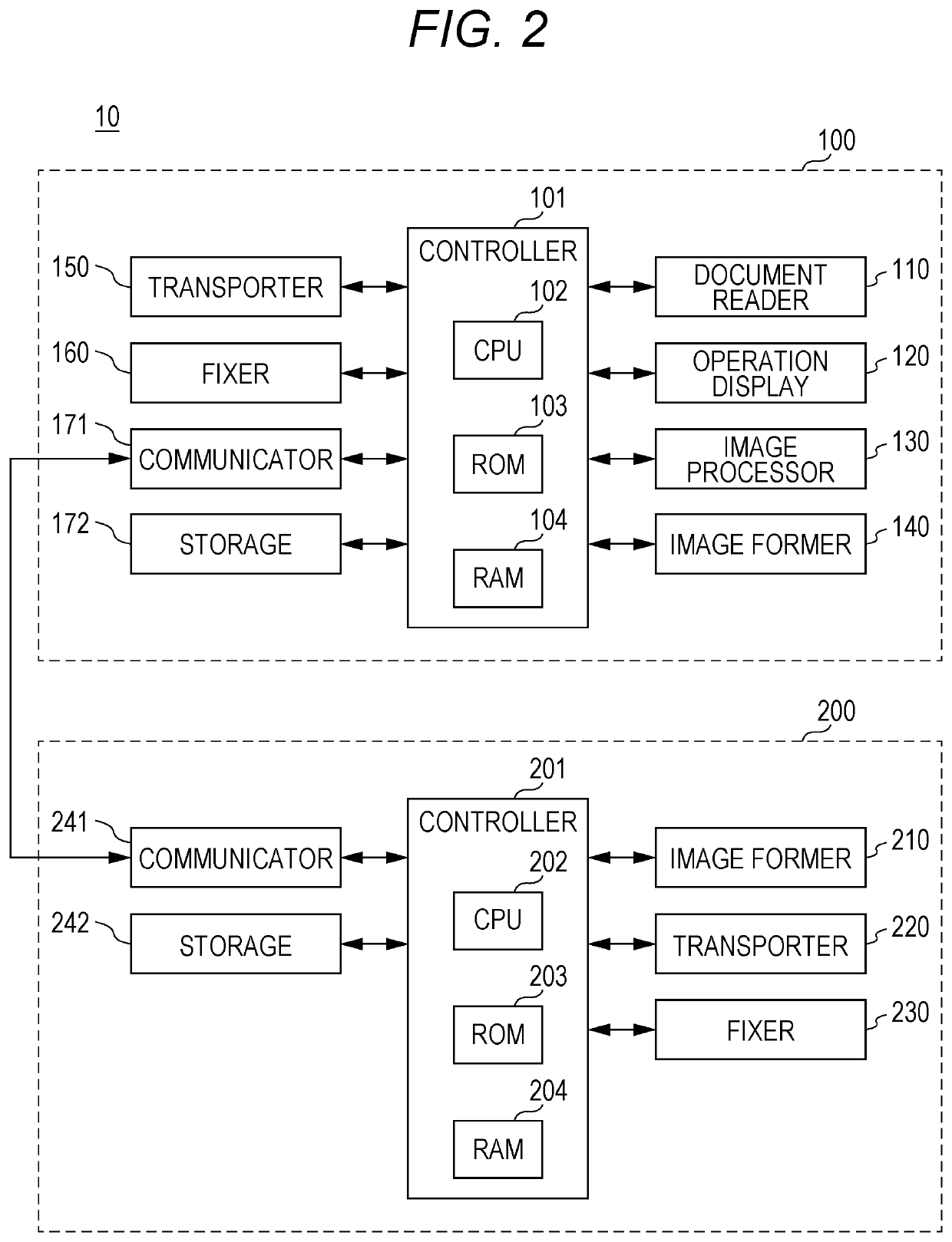
[0030]An image forming system 10 shown in FIG. 1 includes a paper feed tray unit PFU, a first image forming apparatus 100, a second image forming apparatus 200, a post-processing apparatus 300, etc. connected in this order. The first image forming apparatus 100 includes an inversion mechanism R1. The second image forming apparatus 200 includes an inversion mechanism R2. The post-processing apparatus 300 includes an output tray 310. An arrow in the figure indicates a paper transport path. A system including two or more image forming apparatuses connected in series like the image forming system 10 shown in FIG. 1 is generally called a tandem image forming system.

[0031]When performing double-sided printing, the image forming system 10 f...


PUM


Abstract

An image forming system includes: a first image forming apparatus including a first fixer that fixes an image formed on a recording medium to the recording medium; a second image forming apparatus including a second fixer that fixes an image formed on the recording medium to the recording medium, the second image forming apparatus being connected to a downstream side of the first image forming apparatus in a transport direction of the recording medium; and a hardware processor that determines first transport control content in which the recording medium is transported in the first image forming apparatus and the second image forming apparatus, and sets second transport control content so that the recording medium that has been processed by the first fixer is processed in a different position by the second fixer.

Description

CROSS REFERENCE TO RELATED APPLICATIONS[0001]This present invention claims priority under 35 U.S.C. § 119 to Japanese Patent Application No. 2020-084075, filed on May 12, 2020, the entire content of which is incorporated herein by reference.BACKGROUNDTechnological Field[0002]The present invention relates to an image forming system, a transport control method, and a program.Description of the Related Art[0003]In recent years, a tandem image forming system in which two image forming apparatuses are connected in series to perform double-sided printing etc. has been put to practical use (see, for example, JP 2012-203870 A).[0004]Such a tandem image forming system can perform so-called additional printing, in which, for example, a black image is formed on the front side of paper by an upstream image forming apparatus (upstream machine), and, for example, red is additionally formed on the front side of the paper by a downstream image forming apparatus (downstream machine).[0005]Alternativ...

Claims


Application Information

Patent Timeline
Patent Type & Authority Patents(United States)
IPC IPC(8): G03G15/01G03G15/23G03G15/00G03G15/20
CPCG03G15/0194G03G15/0131G03G15/0189G03G15/2021G03G15/231G03G15/238G03G15/6573G03G15/6582G03G15/6585G03G2215/0119
Inventor ISOHARA, HIDEO
Owner KONICA MINOLTA INC
Why Eureka
Try Eureka