
Key structure

Active Publication Date: 2017-06-08
PRIMAX ELECTRONICS LTD
View PDF1 Cites 1 Cited by
  • Summary
  • Abstract
  • Description
  • Claims
  • Application Information

AI Technical Summary

Benefits of technology

The patent describes a key structure that is slim and less likely to get damaged. The key has a special design where a part of the key either protrudes out or is hollowed out to increase its size. This makes the key stronger and less likely to break. The design also allows for easy attachment to the rest of the key structure without being affected by the bulge. The technical effect is a quieter, more durable key design that allows for smooth use and reduced damage.

Problems solved by technology

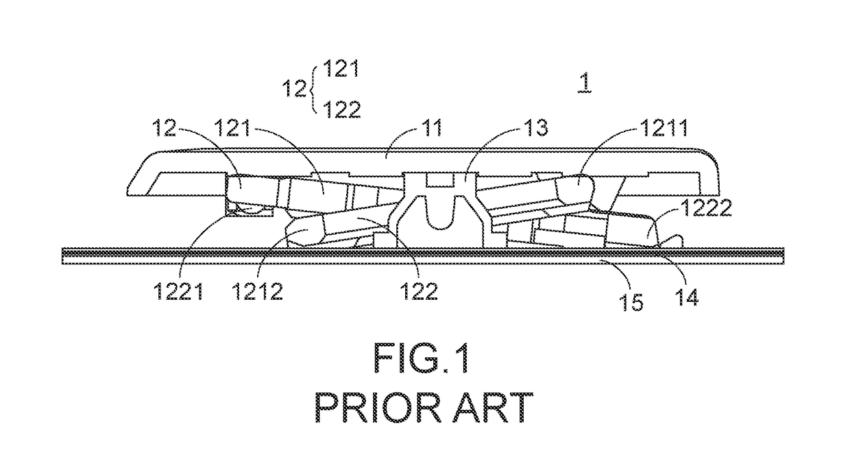
Since the conventional key structure 1 is thinner, some components of the conventional key structure 1 are readily damaged during the assembling process.

Method used


Image

  • Key structure
  • Key structure
  • Key structure

Examples


first embodiment

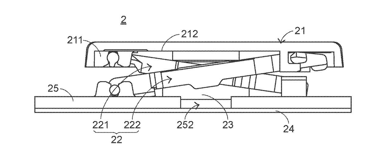
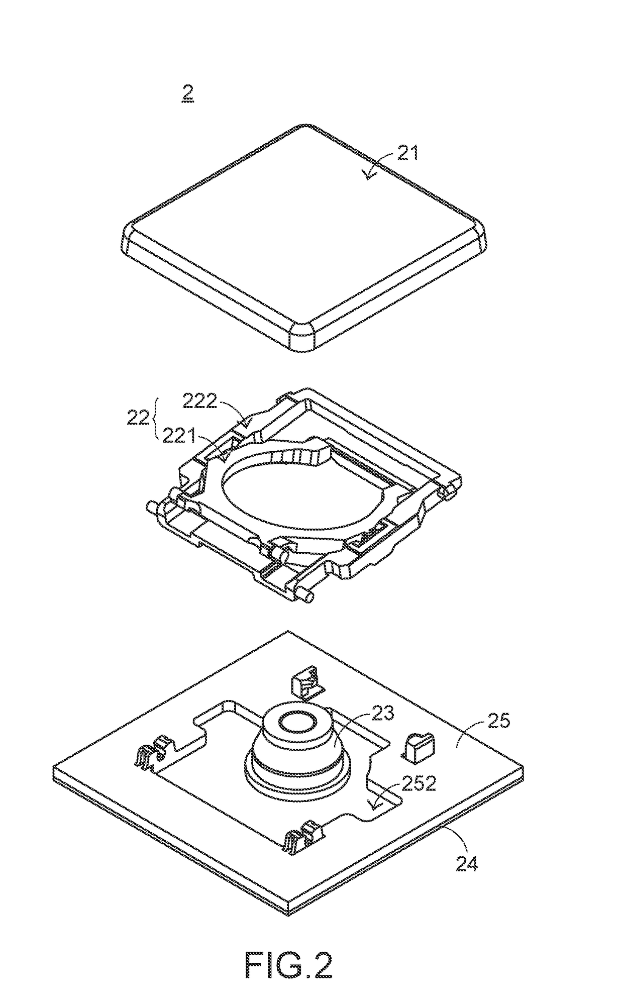
[0028]Hereinafter, the structure of the scissors-type connecting element 22 will be illustrated with reference to FIG. 4. FIG. 4 is a schematic exploded view illustrating the scissors-type connecting element of the key structure according to the present invention. As shown in FIG. 4, the scissors-type connecting element 22 comprises a first frame 221 and a second frame 222. A first end 2214 of the first frame 221 is connected with the keycap 21. A second end 2215 of the first frame 221 is connected with the base 25. Moreover, the first frame 221 comprises a first keycap post 2211, a first base post 2212 and a bulge 2213. The first keycap post 2211 is located at the first end 2214 of the first frame 221, and protruded from a sidewall 2216 of the first frame 221. The first keycap post 2211 is connected with the keycap 21. The first base post 2212 is located at the second end 2215 of the first frame 221, and connected with the base 25. The bulge 2213 is externally extended from the fir...

second embodiment

[0036]Hereinafter, the structure of the scissors-type connecting element 32 will be illustrated with reference to FIG. 8. FIG. 8 is a schematic exploded view illustrating the scissors-type connecting element of the key structure according to the present invention. As shown in FIG. 8, the scissors-type connecting element 32 comprises a first frame 321 and a second frame 332. A first end 3214 of the first frame 321 is connected with the keycap 31. A second end 3215 of the first frame 321 is connected with the base 35. Moreover, the first frame 321 comprises a first keycap post 3211 and a first base post 3212. The first keycap post 3211 is located at the first end 3214 of the first frame 321, and connected with the keycap 31. The first base post 3212 is located at the second end 3215 of the first frame 321, and connected with the base 35.

[0037]The second frame 322 is combined with the first frame 321. A first end 3224 of the second frame 322 is connected with the base 35. A second end ...


PUM


Abstract

A key structure includes a base, a triggering element, a keycap and a scissors-type connecting element. The keycap is disposed over the triggering element. When an external force is applied to the keycap, the triggering element is pushed by the keycap. The scissors-type connecting element is connected with the keycap and the base. The scissors-type connecting element includes a first frame and a second frame. The first frame includes a keycap post, a base post and a bulge. The bulge is externally extended from a first end of the first frame and located at a side of the keycap post, and the bulge is protruded from a sidewall of the first frame. Due to the bulge, the structured strength of the keycap post is enhanced.

Description

FIELD OF THE INVENTION[0001]The present invention relates to a key structure, and more particularly to a key structure with a scissors-type connecting element.BACKGROUND OF THE INVENTION[0002]Generally, the widely-used peripheral input device of a computer system includes for example a mouse, a keyboard, a trackball, or the like. Via the keyboard, characters or symbols can be directly inputted into the computer system. As a consequence, most users and most manufacturers of input devices pay attention to the development of keyboards. As known, a keyboard with scissors-type connecting elements is one of the widely-used keyboards.[0003]Hereinafter, a key structure with a scissors-type connecting element of a conventional keyboard will be illustrated with reference to FIG. 1. FIG. 1 is a schematic side cross-sectional view illustrating a conventional key structure. As shown in FIG. 1, the conventional key structure 1 comprises a keycap 11, a scissors-type connecting element 12, a rubber...

Claims


Application Information

Patent Timeline
IPC IPC(8): H01H13/14
CPCH01H2221/036H01H13/14H01H13/7065H01H2227/03H01H2231/002H01H3/125H01H13/705
Inventor JHUANG, CHUANG-SHUHAN, SONG-HUI
Owner PRIMAX ELECTRONICS LTD
Learn More