
Compact, modular, pump or turbine with integral modular motor or generator and coaxial fluid flow

a technology of modular motors and coaxial fluid flow, applied in the field of integrated sealless pumps and turbines, can solve problems such as the use of dynamic seals, the alignment problem of the motor or generator, and the source of leakage and other failure modes, so as to simplify the overall pump design, reduce the effect of instruments and safe shutting down the system

Active Publication Date: 2022-05-03
FLOWSERVE PTE LTD
View PDF49 Cites 0 Cited by
  • Summary
  • Abstract
  • Description
  • Claims
  • Application Information

AI Technical Summary

Benefits of technology

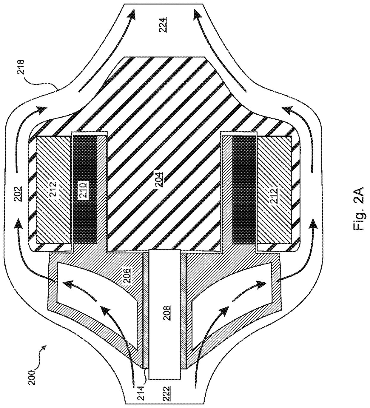
[0027]According to the present invention, the coil housing, i.e. stator housing, of the motor or generator is concentrically surrounded by the outer housing of the module, i.e. the module housing, thereby creating an annular space therebetween surrounding the motor or generator coils and centered on a primary axis of the motor or generator. Working fluid enters the module axially through a proximal inlet that is located substantially along the primary axis, and is discharged axially from the module through a distal outlet that is also located substantially along the primary axis. Within the module, the working fluid flows symmetrically past the stator housing that surrounds the motor or generator coils through either a plurality of substantially identical flow passages arranged symmetrically about the circumference of the stator housing, or through a single, annular flow passage that surrounds the stator housing. This symmetric distribution of the flow passage(s) in the region surrounding the motor or generator coils provides a compact design wherein the module housing is only moderately larger in diameter than the stator housing of the motor or generator.
[0041]Providing individual VFD drives for each stage can also serve as a fail-safe redundancy, whereby if one stage fails, the rest will continue to operate and the apparatus will continue to function. The continued function after failure of a pump or turbine stage may be with reduced head and flow, or the speed of the remaining stages can be increased to compensate for the lost head and flow of the failed stage. This approach creates a failure scenario wherein the pump or turbine continues to operate, possibly at reduced head and flow, until an operator, after becoming aware of the stage failure, has time to safely shut down the system. In contrast, the failure of one stage in a traditional pump or turbine would result in failure of the entire apparatus, with a complete loss of performance and a sudden, uncontrolled shutdown of the system. Using a sensor-less motor along with an appropriate VFD also reduces the instrumentation required on each stage in various embodiments.

Problems solved by technology

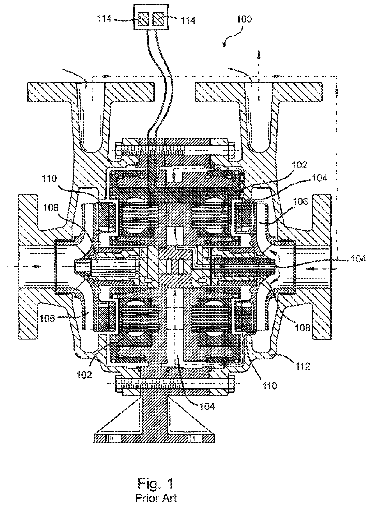
One of the difficulties of these approaches is that they require the use of dynamic seals to maintain the pressure boundaries at the location where the rotating shaft penetrates the stationary pump or turbine casing.
These seals are a source of leakage and other failure modes.
Even with rigid baseplates, nozzle loads on the pump or turbine can cause alignment problems between the motor or generator and the mechanical seals.
However, these designs still require careful alignment of the motor or generator with the rotor housing to couple the motor or generator with the rotor shaft as efficiently as possible.
Also, the components used for magnetic coupling add complexity and cost to the design.
However, radial field designs necessarily require a significant increase in the diameter and length of the rotor housing.
However, it can be difficult to cool the motor or generator coils of an integral sealless motor pump or sealless generator turbine.
Unfortunately, as the shunted fluid passes through passages adjacent to the stator wall, through a hollow rotating shaft, through the shaft bearings, and / or through other appropriate channels, a phase change may occur due to the combination of fluid heating and / or a pressure drop due to the transition from discharge to suction pressure.
The resulting exposure to fluid in the vapor phase can result in motor / generator overheating and / or bearing failure.
Furthermore, the requirement of diverting a certain fraction of the pump output or turbine input into a cooling flow necessarily reduces the efficiency of the pump or turbine.
Another disadvantage of pumps and turbines before the present invention that include a mechanically integral motor or generator is that each pump or turbine design necessarily requires a corresponding, integral motor or generator design.
In addition to the issues that are discussed above, another general problem that is encountered in the design of both integral and non-integral pumps and turbines is how to scale up the capacity of an existing pump or turbine design to meet the requirements of a new application, which generally requires redesigning the physical shape and size of the rotor, operating the rotor at a higher speed, and / or adding additional rotors.
For a given rotor design, the maximum rotor speed is limited by the amount of torque that the motor can develop.
The speed of rotation is also limited by both the frequency limitations of the inverter used to drive the motor and the NPSH (Net Positive Suction Head) available at the inlet of the rotor.
However, the additional size and bulk that result from this approach can be problematic.
However, this approach does not work for sealless motor and generator designs, because the rotor is also a component of the motor or generator.
In particular, in axial sealless designs smaller diameter rotors provide smaller available disk areas for mounting permanent-magnets or inductive magnets, thereby limiting the torque that can be developed by the motor, or the electrical power that can be produced by the generator.
Another limitation is the relative unavailability of sealless motor designs (magnetic rotors and stators) that can deliver a range of pressures and flow rates, and of sealless generator designs that operate efficiently over a range of pressures and flow rates.
However, this approach increases the bulk of the apparatus, because it requires use of a larger and thicker rotor casing and other structural components to contain the larger components and higher fluid pressures.
Increasing output by expanding the number of rotors can also be problematic for any pump or turbine design.
Whether configured in a horizontal or a vertical arrangement, these long shafts with multiple rotor stages require larger bearings and increase the likelihood of bearing failures.
In addition, the long shafts of multi-stage pumps can lead to various roto-dynamic issues related to shaft deflections and critical speeds.
Because of these issues, and for other reasons, each multi-stage pump design is applicable only to a specified maximum number of stages, and cannot be easily scaled to accommodate requirements for different numbers of stages.
Furthermore, the elongated shaft, multi-stage approach requires that all of the rotors rotate at the same speed, which can limit the efficiency and / or NPSH (net positive suction head) performance of the design.
In addition, a failure of any one stage in a multi-stage pump will cause an immediate and total failure of the entire pump or turbine.
However, this approach of combining a plurality of pumps or turbines into a multi-stage apparatus requires the use of bulky and complex fluid interconnections or manifolds, so that excessive space is consumed.
In addition, the reliability of the apparatus is reduced, because the number of hoses and / or other fluid connections, and therefore the opportunities for leaks and / or other failure modes, increases as the number of pumps or turbines is increased.
However, the fluid interconnections and motor / generator cooling requirements of a sealless disk motor design tend to limit this approach to only two stages at most.
However, this approach is, by its nature, limited to only two stages, and there is no obvious approach for expanding the design beyond the two-stage limit.

Method used


Image

  • Compact, modular, pump or turbine with integral modular motor or generator and coaxial fluid flow
  • Compact, modular, pump or turbine with integral modular motor or generator and coaxial fluid flow
  • Compact, modular, pump or turbine with integral modular motor or generator and coaxial fluid flow

Examples


embodiment 200

[0094]The present invention is a “sealless” motor pump or sealless generator turbine that is configured as a module having a “concentric” flow design. As an example, a pump embodiment 200 of the present invention is illustrated in FIG. 2A. It can be seen in the figure that the housing 204 of the motor coils 212, i.e. the stator housing 204, is surrounded by the housing 218 of the module, forming an annular space 202 therebetween. According to the present invention, the working fluid is distributed about the annular space 202, either among a plurality of flow passages or through a single annular flow passage. The distribution of the working fluid in the annular space 202 can be symmetric about the stator housing 204. In the embodiment of FIG. 2A, the annular space 202 serves as an annular flow passage 202 through which the working fluid flows from the inlet 222 to the outlet 224.

[0095]In the embodiment of FIG. 2A, the annular flow passage 202 is in direct thermal contact with the hou...

embodiment 220

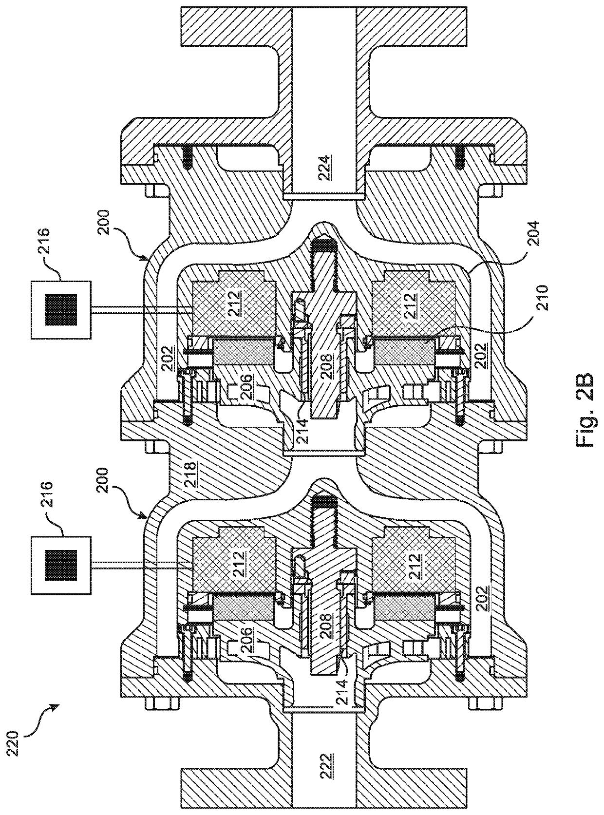
[0097]More specifically, FIG. 2B illustrates a two-stage pump embodiment 220 wherein a central axis of the motor 212 in each stage 200 is substantially collinear with the stationary shaft 208 about which the rotor 206 is rotated, such that the process fluid from the rotor 206 flows axially over the stator housing 204 through the annular flow passage 202 formed between the stator housing 204 and the pump housing 218 in each stage 200. While only two stages 200 are shown in FIG. 2B for convenience of illustration, it will be understood that embodiments are extendable to an arbitrary number of pump stages 200.

[0098]In some multi-stage embodiments, the rotor 206 in each stage 200 is independently driven, such that the rotor speed of each stage 200 can be separately controlled. For example, a separate variable frequency drive (“VFD”) 216 can be dedicated to the control of each stage 200 of the pump.

[0099]In the embodiment of FIG. 2B, in each stage 200 of the pump 220 a plurality of perma...


PUM


Abstract

A coaxial pump or turbine module includes an integral, modular motor or generator comprising a magnet structure containing radial or axial permanent magnets and / or induction coils detachably fixed to a rotor, and a stator housing detachably fixed to the module housing. Working fluid is directed axially through a flow path symmetrically distributed within an annulus formed between the module housing and the stator housing. The stator housing can be cooled by the working fluid, or by a cooling fluid flowing between passages of the flow path. The flow path can extend over substantially a full length and rear surface of the stator housing. A plurality of the modules can be combined into a multi-stage apparatus, with rotor speeds independently controlled by corresponding variable frequency drives. Embodiments include guide vanes and / or diffusers. The rotor can be fixed to a rotating shaft, or rotate about a fixed shaft.

Description

RELATED APPLICATIONS[0001]This application is a continuation in part of U.S. application Ser. No. 16 / 204,997, filed Nov. 29, 2018. Application Ser. No. 16 / 205,997 is a continuation in part of U.S. application Ser. No. 15 / 793,457, filed Oct. 25, 2017. All of these applications are herein incorporated by reference in their entirety for all purposes.FIELD OF THE INVENTION[0002]The invention relates to pumps and turbines, and more particularly, to integral sealless pumps and turbines.BACKGROUND OF THE INVENTION[0003]Rotodynamic pumps and turbines are often highly similar in their physical designs, such that the difference between a pump and a turbine can sometimes be mainly a question of use rather than structure. Accordingly, features of the present invention and of the prior art that are discussed herein with reference to a turbine or to a pump should be understood to refer equally to both, except where the context requires otherwise.[0004]In a conventional rotodynamic pump design, fl...

Claims


Application Information

Patent Timeline
Patent Type & Authority Patents(United States)
IPC IPC(8): F04D1/06H02K5/20H02K5/167H02K5/22H02K9/193H02K7/08F04D13/14F04D1/08F04D13/06
CPCH02K5/20F04D1/066F04D1/08F04D13/0666F04D13/14H02K5/1677H02K5/225H02K7/088H02K9/193H02K2205/03H02K2213/12H02K5/203
Inventor JUDGE, SCOTT C.DREISS, ANDREASHAVRILLA, NEILOLEXSON, JR., DAVID
Owner FLOWSERVE PTE LTD
Learn More