Graphical user interface for medical imaging system

a medical imaging and user interface technology, applied in medical science, diagnostics, surgery, etc., can solve problems such as asynchronous rhythm and disruption of normal cardiac cycle, and achieve the effect of facilitating efficient processing of information by the operator

Active Publication Date: 2022-05-10
BIOSENSE WEBSTER (ISRAEL) LTD
View PDF32 Cites 8 Cited by
  • Summary
  • Abstract
  • Description
  • Claims
  • Application Information

AI Technical Summary

Benefits of technology

[0005]Electrical activity in the heart is typically measured by advancing a multiple-electrode catheter to measure electrical activity at multiple points in the heart chamber simultaneously. A graphical user interface integrated with modern imaging systems for monitoring cardiac catheterization presents an abundance of dynamically changing information from the multiple electrodes to the operator, and facilitates efficient processing of the information by the operator.

Problems solved by technology

Cardiac arrhythmias, such as atrial fibrillation, occur when regions of cardiac tissue abnormally conduct electric signals to adjacent tissue, thereby disrupting the normal cardiac cycle and causing asynchronous rhythm.

Method used


Image

  • Graphical user interface for medical imaging system
  • Graphical user interface for medical imaging system
  • Graphical user interface for medical imaging system

Examples


first alternate embodiment

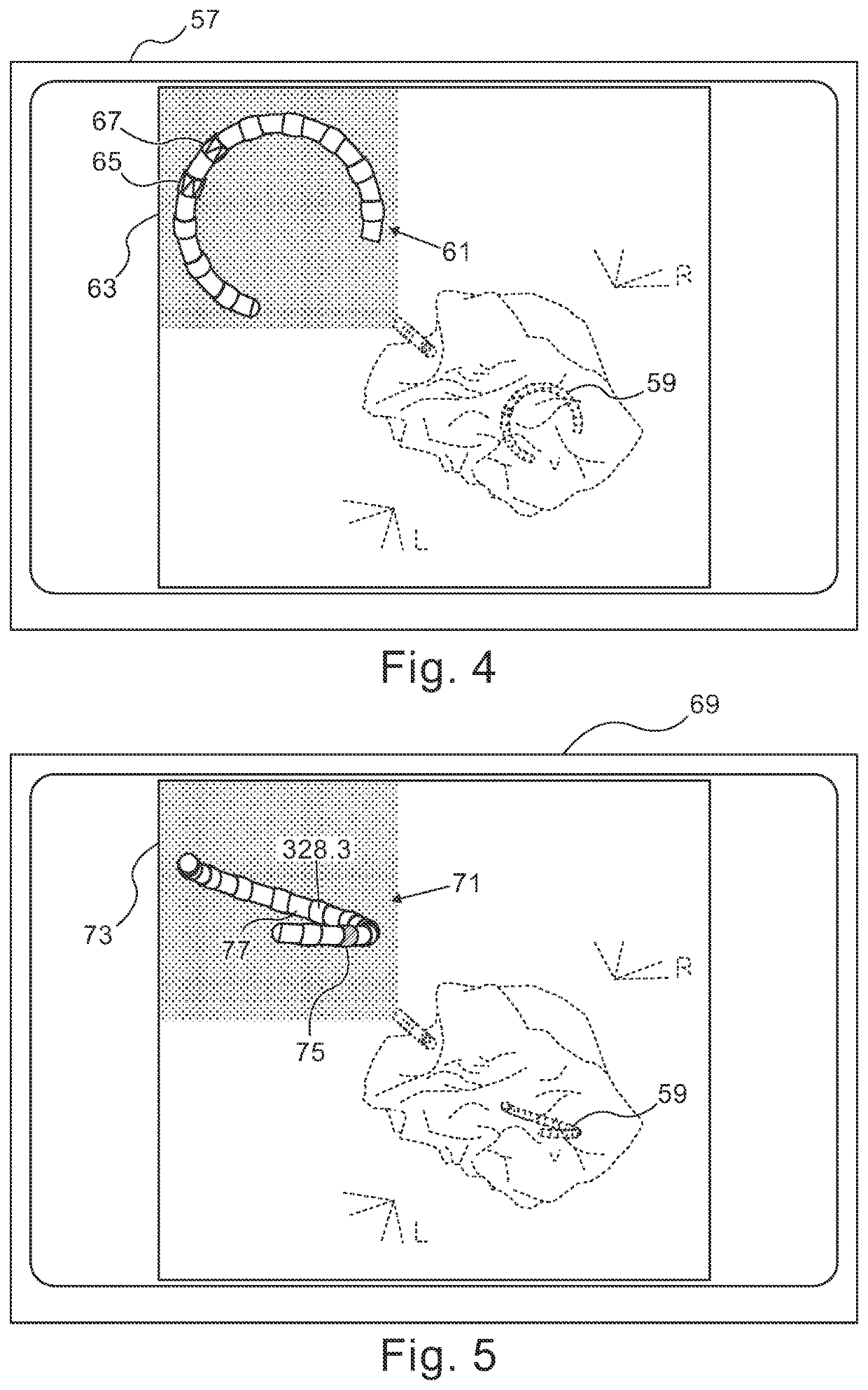
[0046]Reference is now made to FIG. 4, which is a screen display 57 in accordance with an embodiment of the invention. The screen display 51 is similar to the screen display 37 (FIG. 2), except that catheter 59 is a loop or lasso having multiple ring electrodes, as best seen in a catheter image 61 in icon 63. Ring electrodes 65, 67 (shown in hatched pattern) are visually apparent as being actively in use as bipolar sensors.

[0047]Reference is now made to FIG. 5, which is a screen display 69 in accordance with an embodiment of the invention. The screen display 69 is similar to the screen display 57 (FIG. 4), except that the catheter 59 has a different orientation, having a partial spiral twist. In the catheter image 71 within icon 73, one ring electrode 75 is currently active, and is readily distinguished from its fellows by a visual effect, indicated here by a hatching pattern. Status information (328.3) is displayed with respect to another ring electrode 77. It will be appreciated t...

second alternate embodiment

[0048]Reference is now made to FIG. 6, which is a screen display 79 in accordance with an alternate embodiment of the invention. This embodiment is similar to the embodiment shown in FIG. 5, except now in icon 81 the ring electrodes 65, 67 in catheter image 83 are visually emphasized by visual cues (circles). Alternatively, when the cued elements are sensors, such cues could indicate a normal or abnormal functional status; e.g., insufficient or excessive pressure or temperature. As the status of the electrodes and sensors changes dynamically during the procedure, it is important that the operator be alerted to abnormal conditions.

third alternate embodiment

[0049]Reference is now made to FIG. 7, which is a screen display 85 in accordance with an alternate embodiment of the invention. This embodiment is similar to the embodiment shown in FIG. 4. Icon 87 includes catheter image 89 However ring electrodes 91, 93, 95, 97, 99 are now associated with numbers. Numerical indicia of this sort may be correlated with tabular information or the like that is external to the screen display. Additionally or alternatively, such numbers may indicate actual readings of sensors or the current passing through an ablation electrode. Many types of useful sensors may be incorporated in the catheter and their condition represented on the catheter image 89.


PUM


Abstract

While obtaining electrophysiologic data from a cardiac catheter a series of visual displays are presented. The displays include a respective current image of the heart and the distal portion of the cardiac catheter therein and further include a catheter icon that represents the distal portion of the cardiac catheter, The catheter icon is separated from the image of the heart in the displays. The catheter icon has indicia that represent functional elements of the cardiac catheter.

Description

CROSS-REFERENCE TO RELATED APPLICATIONS[0001]This Application claims the benefit of U.S. Provisional Application No. 61 / 867,664, which is herein incorporated by reference.BACKGROUND OF THE INVENTIONField of the Invention[0002]This invention relates to medical imaging systems. More particularly, this invention relates to improvements in cardiac catheterization.Description of the Related Art[0003]Cardiac arrhythmias, such as atrial fibrillation, occur when regions of cardiac tissue abnormally conduct electric signals to adjacent tissue, thereby disrupting the normal cardiac cycle and causing asynchronous rhythm.[0004]Procedures for treating arrhythmia include locating and surgically disrupting the origin of the signals causing the arrhythmia, as well as disrupting the conducting pathway for such signals. By selectively ablating cardiac tissue by application of energy via a catheter, it is sometimes possible to interrupt or modify the propagation of unwanted electrical signals from one...

Claims


Application Information

Patent Timeline
Patent Type & Authority Patents(United States)
IPC IPC(8): A61B5/06A61B5/00A61B34/00A61B5/0538A61B5/283A61B5/318
CPCA61B5/061A61B5/743A61B34/25A61B5/0538A61B5/062A61B5/063A61B5/283A61B5/318A61B5/7425
Inventor MERSCHON, ASAFINGEL, MOSHEADI, LIAV MOSHEFILIPOV, EDUARD
Owner BIOSENSE WEBSTER (ISRAEL) LTD
Why Eureka
Try Eureka