Supercharge Your Innovation With Domain-Expert AI Agents!

Method of winding

a winding and wire technology, applied in the direction of coil arrangement, induction heating, electrical equipment, etc., can solve the problems of affecting electrical and/or thermal insulation, reducing negating the tendency of small lengths of winding to separate or bulge, etc., to reduce the risk of damage, reduce the incidence of breakage, and relieve the stress of wire generated during compaction

Active Publication Date: 2022-05-10
ADVANCED TECH EMISSION SOLUTIONS
View PDF6 Cites 0 Cited by
  • Summary
  • Abstract
  • Description
  • Claims
  • Application Information

AI Technical Summary

Benefits of technology

[0004]To further reduce the risk of damage during can formation, according to an aspect of the invention, in a method of winding the induction wire around and onto the surface of a former to form a coil, one or more perturbations are introduced into each winding, the perturbation being formed in a length of wire less than the full length of a respective turn or winding. The perturbation is laid so as to project along the surface of the former. The perturbation has an initial shape and size such that when a surrounding jacket is uniformly radially collapsed down onto the coil to compact the coil against a non-compressible core. Resulting stresses in the wire generated during compaction are relieved by alteration of the perturbation from an initial shape and size to a subsequent shape and size.
[0005]One effect of winding the induction wire in this way is to reduce the incidence of breakage when the coil is forced radially inwardly in the course of collapsing the can material and onto an induction heating (IH) gaseous emissions treatment assembly. Coil breakage would render the final assembly useless because the required magnetic field for heating could not be generated. The winding method also negates to some extent the tendency for small lengths of the winding to separate or bulge from the surface of IH interior elements during compaction. Such wire distortion could have any of a number of adverse effects, one being the tearing of compressible fibrous matting adjacent the coil in the IH assembly which could affect the electrical and / or thermal insulation and also increase the risk of vibration damage. Distortion can also cause overlapping of induction coil turns resulting, in turn, in electrical interference and / or damage to the wire. Wire distortion can also result in damage to the wire insulation sheath if wire is caused to bear against a hard part of the assembly such as the MFC, the ceramic or another coil winding. Damage to the sheath can reduce the electrical insulating value with an attendant risk of shorting or reduced lifespan. The ceramic substrate is quite fragile and bulging in one part of the winding can reduce the winding diameter in an adjacent part of the winding. This, in turn can cause deflection into the ceramic with possible piercing of the thin walls and consequent direct exposure of the coil to hot exhaust gas when the converter is in use. Another adverse effect is that the collapsing down of the outer jacket may cause a coil turn at the end of the coil to jump out of the MFC. Typically, the coil resides in a pocket or recess in the MFC for maximum electromagnetic efficiency. If the last winding jumps from the pocket, this will distort the electromagnetic signature and thus the efficiency.

Problems solved by technology

Coil breakage would render the final assembly useless because the required magnetic field for heating could not be generated.
The winding method also negates to some extent the tendency for small lengths of the winding to separate or bulge from the surface of IH interior elements during compaction.
Such wire distortion could have any of a number of adverse effects, one being the tearing of compressible fibrous matting adjacent the coil in the IH assembly which could affect the electrical and / or thermal insulation and also increase the risk of vibration damage.
Distortion can also cause overlapping of induction coil turns resulting, in turn, in electrical interference and / or damage to the wire.
Wire distortion can also result in damage to the wire insulation sheath if wire is caused to bear against a hard part of the assembly such as the MFC, the ceramic or another coil winding.
Damage to the sheath can reduce the electrical insulating value with an attendant risk of shorting or reduced lifespan.
The ceramic substrate is quite fragile and bulging in one part of the winding can reduce the winding diameter in an adjacent part of the winding.
This, in turn can cause deflection into the ceramic with possible piercing of the thin walls and consequent direct exposure of the coil to hot exhaust gas when the converter is in use.
Another adverse effect is that the collapsing down of the outer jacket may cause a coil turn at the end of the coil to jump out of the MFC.

Method used


Image

  • Method of winding
  • Method of winding

Examples


Embodiment Construction

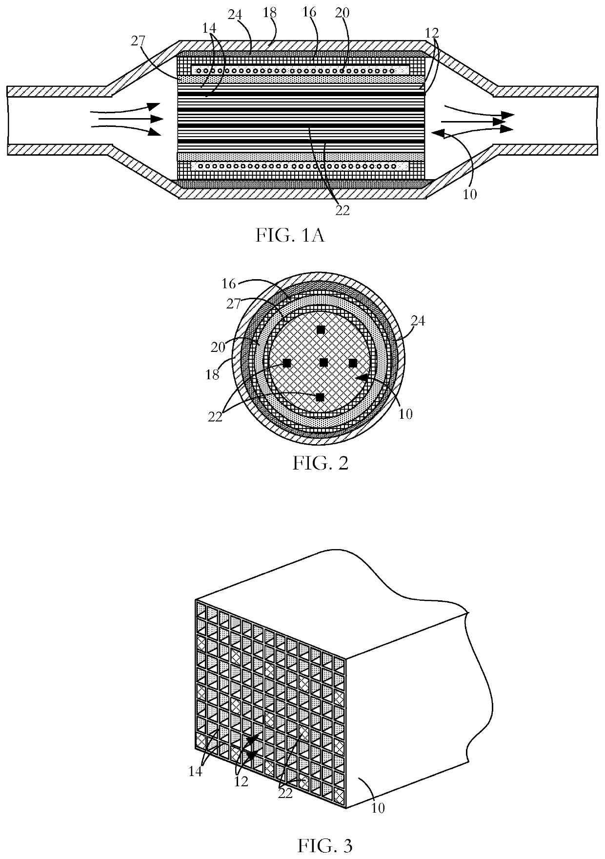
[0014]A gaseous emissions treatment assembly may take any of a number of forms. Typical of these is a catalytic converter formed as a concentric assembly and having a cylindrical substrate body 10 usually made of ceramic material and often called a brick, an example of which is shown in FIGS. 1A and 2. The brick has a honeycomb structure in which a number of small area passages or cells 12 extend the length of the brick, the cells being separated by walls 14. There are typically from 400 to 900 cells per square inch (cpsi) of cross-sectional area of the substrate body 10 and the walls are typically in the range 0.003 to 0.008 inches in thickness. Typically, the ceramic substrate body 10 is formed in an extrusion process in which green ceramic material is extruded through an appropriately shaped die and units are cut successively from the extrusion, the units being then cut into bricks. The areal shape of the cells or passages 12 may be whatever is convenient for contributing to the ...


PUM

PropertyMeasurementUnit
thicknessaaaaaaaaaa
temperatureaaaaaaaaaa
RMS voltageaaaaaaaaaa

Abstract

As wire is wound around and onto the surface of a former to form a coil, perturbations such as waves are introduced into turns of the coil, each perturbation being formed in a length of the wire less than the full length of a respective turn and projecting along the former surface, the perturbation having an initial shape and size. The coil is taken from the former and fixed in form. A surrounding jacket is radially collapsed onto the wire coil to uniformly press the coil against an internal compressible body in the course of which the overall diameter of the coil is reduced. Resulting stresses in the wire generated during the collapse are relieved by alteration of the perturbations from their initial shape and size to a subsequent shape and size.

Description

FIELD OF THE INVENTION[0001]This invention relates to a method of winding and has particular application to winding induction heating wire for use in an induction heated gaseous emissions treatment unit.BACKGROUND[0002]Catalytic converters, particulate filters and like assemblies for installation in vehicles generally have an outer housing or can. In use, emissions gas is delivered to the assembly by an exhaust pipe and treated gas leaves the converter through a tail pipe. In the course of assembly, a sheet metal jacket is collapsed down onto interior components of the assembly to form the can. Typically, such an assembly has a ceramic substrate body along which extend cells for the passage of exhaust gas which is treated while in the cells to render the gas less noxious. Such treatment occurs in the course of chemical reactions that require the assembly to reach a sufficiently high, so-called ‘light off’ temperature. U.S. Pat. No. 9,488,085 describes a structure and method for indu...

Claims


Application Information

Patent Timeline
Patent Type & Authority Patents(United States)
IPC IPC(8): H01F41/066H05B6/36H01F41/064H01F41/071
CPCH01F41/066H01F41/064H01F41/071H05B6/36F01N3/2013F01N3/027H05B6/108Y02T10/12
Inventor CRAWFORD, ROBINDOUGLAS, JOHN
Owner ADVANCED TECH EMISSION SOLUTIONS
Features
  • R&D
  • Intellectual Property
  • Life Sciences
  • Materials
  • Tech Scout
  • Unparalleled Data Quality
  • Higher Quality Content
  • 60% Fewer Hallucinations
Learn More