Engagement structure of cover and block member, electronic component module, electrical connection box, and wire harness
a technology of electronic components and block members, which is applied in the direction of fixed connections, casings/cabinets/drawers, casings/cabinets/drawers details, etc., can solve the problems of connector blocks or substrates being detached from cases, the state of engagement of the engagement mechanism becoming unstable, and the occlusion of the cover and block member. to achieve the effect of facilitating the attachment of the electronic component module to the body of the automobil
- Summary
- Abstract
- Description
- Claims
- Application Information
AI Technical Summary
Benefits of technology
Problems solved by technology
Method used
Image
Examples
first embodiment
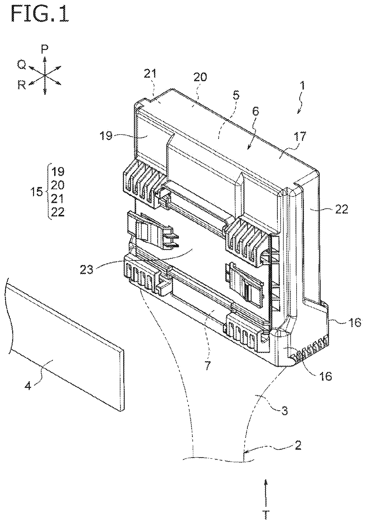
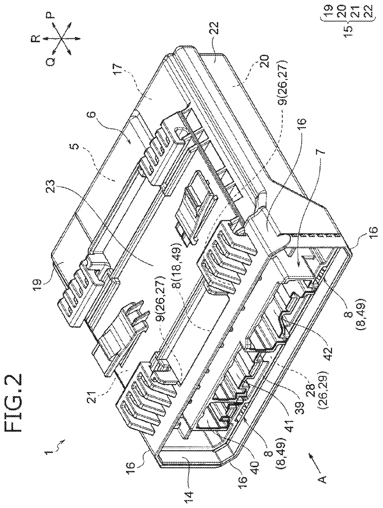
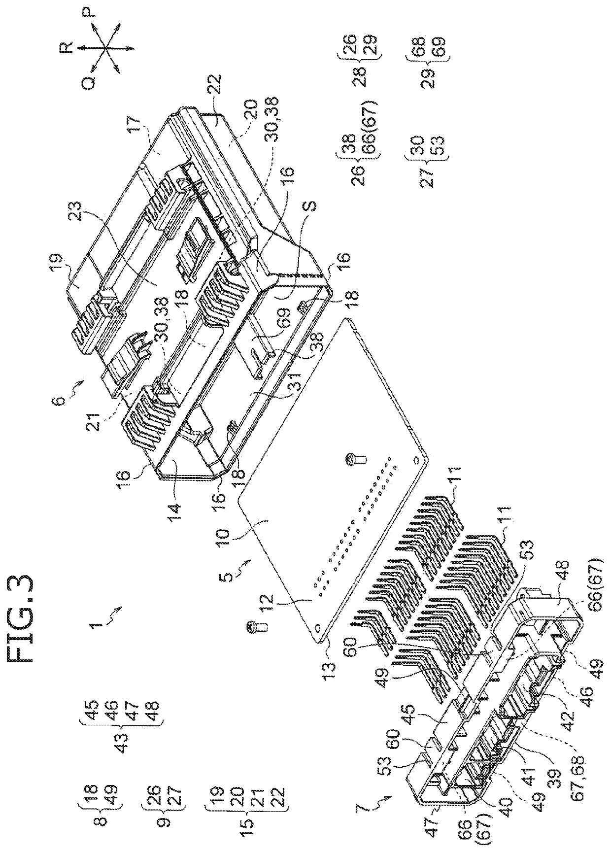
[0077]A first embodiment will be described below with reference to the drawings. FIG. 1 is a perspective view illustrating an electronic component module according to an embodiment of the present invention. FIG. 2 is a perspective view of the electronic component module in FIG. 1 as viewed from an arrow T direction. FIG. 3 is an exploded perspective view illustrating a configuration of the electronic component module. FIG. 4 is a view of the electronic component module in FIG. 2 as viewed from an arrow A direction. FIG. 5 is a cross-sectional view illustrating an engagement mechanism at a position of a line B-B in FIG. 4. FIGS. 6A and 6B illustrate a cover. FIGS. 7A and 7B illustrate a cover side lock portion. FIGS. 8A and 8B illustrate a convex portion of a second stabilization mechanism. FIGS. 9A to 11B illustrate a connector block. FIGS. 12A and 12B illustrate a block side lock portion. FIGS. 13A and 13B illustrate a second stabilization mechanism and a first stabilization mechan...
second embodiment
[0140]A second embodiment will be described below with reference to the drawings. FIGS. 16A, 16B, 16C, and 16D illustrate a modification of the first stabilization mechanism, in which FIG. 16A illustrates excessive insertion due to backlash that occurs in the engagement mechanism, FIG. 16B is a cross-sectional view taken along a line V-V in FIG. 16A, FIG. 16C illustrates a backlash preventing condition, and FIG. 16D is a cross-sectional view taken along a line W-W in FIG. 16C.
[0141]70 and Connector Block 71>
[0142]In FIG. 16A, the connector block 71 is inserted into and engaged with the opening portion of the cover 70. In the engagement mechanism 72, a rectangular hole-shaped cover side lock portion 73 formed in the cover 70 and a convex block side lock portion 74 formed in the connector block 71 are engaged. When the hole-shaped cover side lock portion 73 and the convex block side lock portion 74 are engaged, excessive insertion (over-stroke) is generally required. This excessive in...
PUM
 Abstract
Description
Claims
Application Information
 - R&D
- Intellectual Property
- Life Sciences
- Materials
- Tech Scout
- Unparalleled Data Quality
- Higher Quality Content
- 60% Fewer Hallucinations
Browse by: Latest US Patents, China's latest patents, Technical Efficacy Thesaurus, Application Domain, Technology Topic, Popular Technical Reports.
© 2025 PatSnap. All rights reserved.Legal|Privacy policy|Modern Slavery Act Transparency Statement|Sitemap|About US| Contact US: help@patsnap.com


