Method for boil detection and induction hob including a boil detection mechanism

a technology of induction hob and detection mechanism, which is applied in the direction of lighting and heating apparatus, heating types, stoves or ranges, etc., can solve the problems of unsatisfactory accuracy of boil point detection, and achieve the effect of reliable and robustness

Active Publication Date: 2022-05-10
ELECTROLUX APPLIANCES
View PDF8 Cites 0 Cited by
  • Summary
  • Abstract
  • Description
  • Claims
  • Application Information

AI Technical Summary

Benefits of technology

[0005]It is an objective of the embodiments of the invention to provide a reliable and robust method for detecting boil point in induction hobs using electrical parameters available within the induction hob. If not explicitly indicated otherwise, embodiments of the invention can be freely combined with each other.

Problems solved by technology

A drawback of the known solution is that the accuracy of boil point detection is no satisfactory because certain detrimental influences lead to a wrong boil point detection result.

Method used


Image

  • Method for boil detection and induction hob including a boil detection mechanism
  • Method for boil detection and induction hob including a boil detection mechanism

Examples


Embodiment Construction

[0037]The present invention will now be described more fully with reference to the accompanying drawings, in which example embodiments are shown. However, this invention should not be construed as limited to the embodiments set forth herein. Throughout the following description similar reference numerals have been used to denote similar elements, parts, items or features, when applicable.

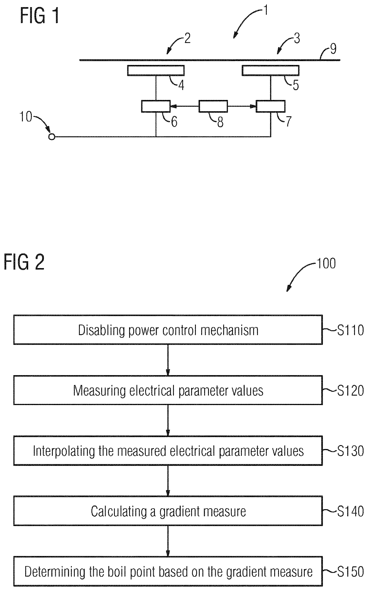
[0038]FIG. 1 shows a schematic illustration of an induction hob 1. The induction hob 1 comprises at least one induction heater 2, 3, preferably provided at a hob plate 9. Beneath the hop plate 9, one or more induction coils 4, 5 are provided wherein each induction heater 2, 3 is associated with one or more induction coils 4, 5. Each induction coil 4 is coupled with electronic driving means 6, 7. Said electronic driving means 6, 7 are coupled with a mains supply 10. Furthermore, a control unit 8 is provided for controlling the operation of the electronic driving means 6, 7, specifically for adjusting...


PUM


Abstract

The invention relates to a method for boil detection at a heating zone of an induction hob (1), the method comprising the steps of: —disabling (S110) a power control mechanism of the induction hob by setting the frequency of the AC-current provided to an induction coil of the induction hob to a fixed value; —measuring (S120) values of an electrical parameter provided within the induction hob (1); —interpolating (S130) the measured electrical parameter values by gathering a plurality of values of the electrical parameter within a time window and calculating the average value of said gathered plurality of values thereby obtaining interpolated electrical parameter values. —calculating (S140) a gradient measure indicative for the differential change of the interpolated electrical parameter values over time; —determining (S150) the boil point based on the calculated gradient measure.

Description

[0001]The present invention relates generally to the field of boil detection. More specifically, the present invention is related to boil detection by monitoring electrical parameters of an induction hob.BACKGROUND OF THE INVENTION[0002]Induction hobs for preparing food are well known in prior art. Induction hobs typically comprise at least one induction heater which is associated with at least one induction coil. For heating a piece of cookware placed on the induction hob, the induction coil is coupled with electronic driving means for driving an AC current through the induction coil. Said AC current generates a time verifying magnetic field. Due to the inductive coupling between the inductor coil and the piece of cookware placed on the induction hob, the magnetic field generated by the inductor coil causes eddy currents circulating in the piece of cookware. The presence of said eddy currents generates heat within the piece of cookware due to the electrical resistance of said piece...

Claims


Application Information

Patent Timeline
Patent Type & Authority Patents(United States)
IPC IPC(8): H05B6/06F24C15/10H05B1/02H05B6/12
CPCH05B6/062F24C15/106H05B1/0269H05B6/12H05B2213/05H05B2213/07
Inventor TERRACCIANO, NICOLAJEANNETEAU, LAURENTVIROLI, ALEXNOSTRO, MASSIMOCHRISTIANSEN, SVEND ERIK
Owner ELECTROLUX APPLIANCES
Why Eureka
Try Eureka