Drive control system for light-emitting diode string

a control system and light-emitting diode technology, applied in the direction of electrical equipment, etc., can solve the problems of high failure rate during use, complicated circuit, unfavorable cost control, etc., and achieve the effects of more economical and practical effects, more stable power supply and signal transmission, and high driving capability

Active Publication Date: 2022-05-17
ZHAO HONGCHUN
View PDF19 Cites 0 Cited by
  • Summary
  • Abstract
  • Description
  • Claims
  • Application Information

AI Technical Summary

Benefits of technology

[0006]A technical problem to be solved by the present disclosure is to provide a two-wire drive control system for a light-emitting diode string, in which a negative electrode of the string is driven by electrically connecting a signal generating unit to a cathode terminal of light-emitting diodes; the system has strong driving capability, which facilitates driving light-emitting diode strings of various connecting modes; and the signal generating unit can be implemented by a switching element and a voltage stabilizing element, so that the circuit of the present disclosure is simple and the product cost is reduced; moreover, the light-emitting diodes of the present disclosure may be connected in series, or in parallel, or in a combination of the two modes, thereby solving the above technical problems.
[0022]The present disclosure has the following beneficial effects: The present disclosure implements negative electrode drive of the string by electrically connecting the signal generating unit to the cathode terminal of the light-emitting diodes, and the control unit can control the switching element to be turned on / off without a high voltage. There is no need to boost the voltage between the control unit and the string. Regardless of the number of the light-emitting diode strings, and the connecting mode of the light-emitting diode string, the control voltage of the switching unit does not need to be changed. The system has higher driving capability than in a positive electrode drive mode, while the string is difficult to drive in the positive electrode drive mode if the power of the string is high. The signal generating unit in the present disclosure only needs two electronic components (such as a CMOS transistor and a voltage stabilizing diode) to drive the light-emitting diodes to emit light. Therefore, the circuit of the present disclosure is simple and can achieve more economical and practical effects. In addition, because the present disclosure can drive the light-emitting diodes without providing a second voltage source, the power supply and signal transmission are more stable in the present disclosure.

Problems solved by technology

A series-connected string has a plurality of light-emitting diodes connected in series, and has a high failure rate during use.
If one light-emitting diode fails, all other light-emitting diodes cannot be turned on.
As a drive control circuit in this patent uses a positive electrode of the light-emitting diode string to implement drive, and a power supply voltage of a main control circuit of the system is lower than that of the light-emitting diode string, the control circuit cannot normally control the on / off of the switching unit, and thus this patent usually can only be used to control and drive a single light-emitting diode string, and the connection of the light-emitting diode string is limited to a parallel connection mode, and it cannot be used for driving 2 or more light-emitting diode strings, or a light-emitting diode string connected in series.
In practice, when 2 or more light-emitting diode strings need to be driven, a large number of electronic components are usually required, and a complicated circuit is not conducive to cost control.
Moreover, this patent is also limited by the weak power supply capability of the second power source, and cannot achieve a good driving effect when the number of light-emitting diode strings is large.
Further, Chinese Patent CN102696282 also proposes a light-emitting diode driving solution, but its technical solution is obviously limited to driving a light-emitting diode string connected in series.
As a result, circuits and lines of the light-emitting string drive control system are very complicated, which is not conducive to cost control of a product on the one hand, and has an adverse effect on the simplicity and beauty of the product on the other hand.

Method used


Image

  • Drive control system for light-emitting diode string
  • Drive control system for light-emitting diode string
  • Drive control system for light-emitting diode string

Examples


Embodiment Construction

[0037]The structural principle and working principle of the present disclosure will be described in detail below in conjunction with the accompanying drawings:

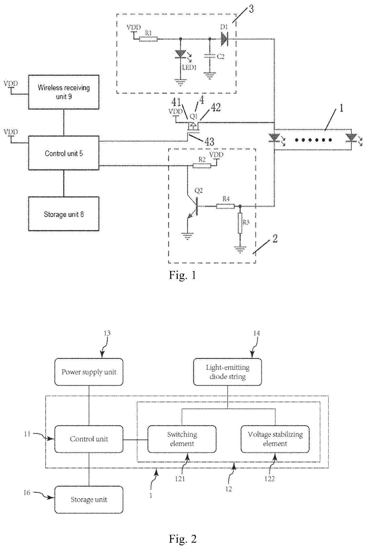
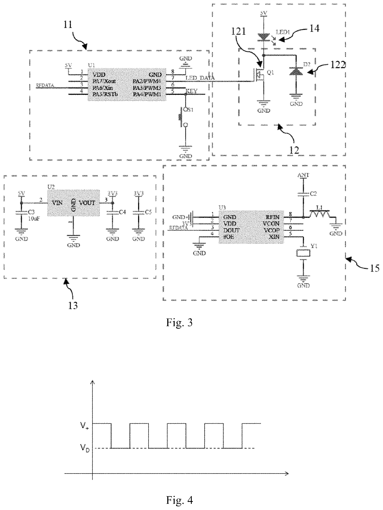
[0038]As shown in FIGS. 2 and 3, FIG. 2 is a block diagram of a drive control system for a plurality of light-emitting diode strings in an embodiment of the present disclosure, and FIG. 3 is a circuit diagram of a drive control system for a plurality of light-emitting diode strings in an embodiment of the present disclosure.

[0039]The two-wire drive control system for a light-emitting diode string of the present disclosure can be mainly used for drive control of a plurality of light-emitting diode strings connected in parallel or in series.

[0040]As shown in FIG. 2, in the embodiment of the present disclosure, the two-wire drive control system 1 for a light-emitting diode string includes a control unit 11 and a signal generating unit 12, wherein one end of the control unit 11 is electrically connected to a power supply unit 13, ...


PUM


Abstract

The present disclosure relates to a drive control system for a light-emitting diode string, comprising a control unit and a signal-generating unit. The signal-generating unit comprises a switching element with a first terminal, a second terminal and a control terminal. One end of the control unit is connected to the control terminal, and the second terminal is connected to a negative terminal of the light-emitting diode string. A voltage stabilizing circuit is connected to the negative terminal of the light-emitting diode string, wherein a positive terminal of the light-emitting diode string is connected to a power supply unit. When the control unit turns on the switching element, the power supply unit directly drives the light-emitting diode string to emit light. When the control unit turns off the switching element, the power supply unit drives the light-emitting diode string to emit light through the voltage stabilizing circuit.

Description

TECHNICAL FIELD[0001]The disclosure relates to a drive control system for a light-emitting string, in particular to a drive control system for a light-emitting diode string.BACKGROUND ART[0002]Currently, connecting modes of light-emitting diode strings generally include series connection and parallel connection. A series-connected string has a plurality of light-emitting diodes connected in series, and has a high failure rate during use. If one light-emitting diode fails, all other light-emitting diodes cannot be turned on. Thus, currently most light-emitting diode strings adopt the parallel connection mode. For example, Chinese patent CN210274608U discloses a control system for a light-emitting diode string, as shown in FIG. 1. The drive control system drives the light-emitting diode string to achieve light emission change by using a light emission control command sent by the control unit to light-emitting diodes. The control unit controls the on / off of a switching unit and coopera...

Claims


Application Information

Patent Timeline
Patent Type & Authority Patents(United States)
IPC IPC(8): H05B45/34H05B45/44
CPCH05B45/34H05B45/44H05B45/30
Inventor ZHAO, HONGCHUN
Owner ZHAO HONGCHUN
Why Eureka
Try Eureka