Dose setting mechanism

a technology of a setting mechanism and a spring, which is applied in the direction of infusion syringes, other medical devices, intravenous devices, etc., can solve the problems of damage to the components of injection devices, and achieve the effect of increasing the energy stored by the spring

Active Publication Date: 2022-05-24
NORTON HEALTHCARE
View PDF10 Cites 0 Cited by
  • Summary
  • Abstract
  • Description
  • Claims
  • Application Information

AI Technical Summary

Benefits of technology

[0020]The assembly of three components provides greater reliability during dose selection. The splines for disengaging the ratchet improve the smoothness of operation during decrementing of the dose. Having a single ratchet component serves two functions, interacting with both the dose selector and the drive plate, which makes the dose setting more reliable.
[0022]In an embodiment, the injection device further comprises an over-torque feature located between the dose selector and the spring, the over-torque feature being actuatable, when the rotation of the dose selector causes the charging force to exceed a defined limit, to reduce the charging force transferred from the dose selector to the spring. Preferably, the over-torque feature is capable of reducing the charging force transferred from the dose selector to the spring to substantially zero.

Problems solved by technology

A disadvantage of this arrangement is that, should the user continue to attempt to increase the dose, damage to components of the injection device may occur.

Method used


Image

  • Dose setting mechanism
  • Dose setting mechanism
  • Dose setting mechanism

Examples


example embodiment

Description of Example Embodiment

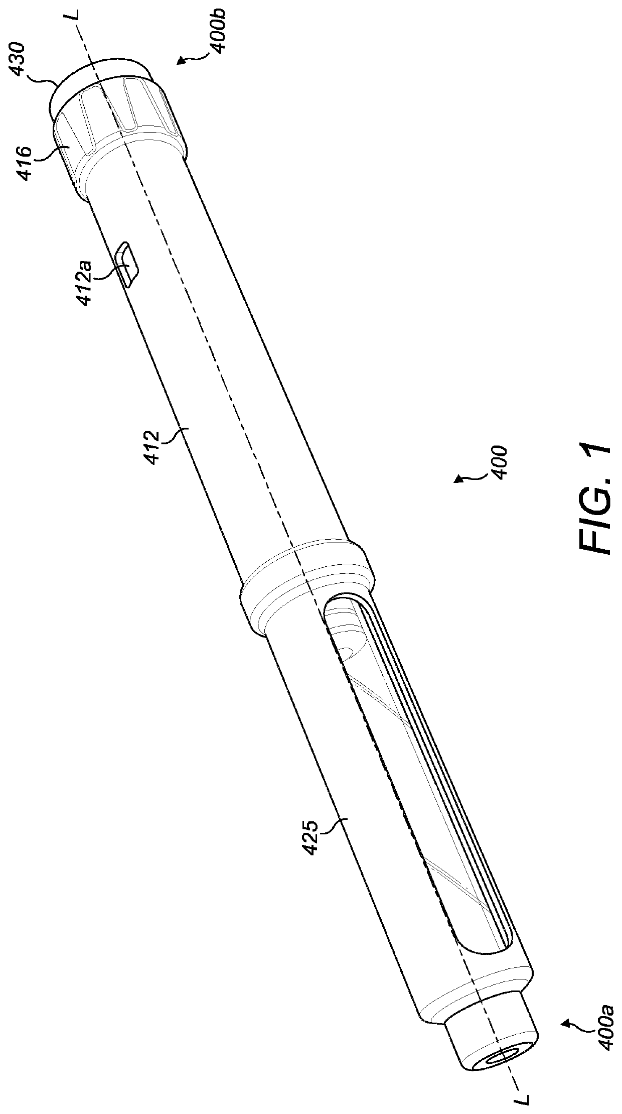
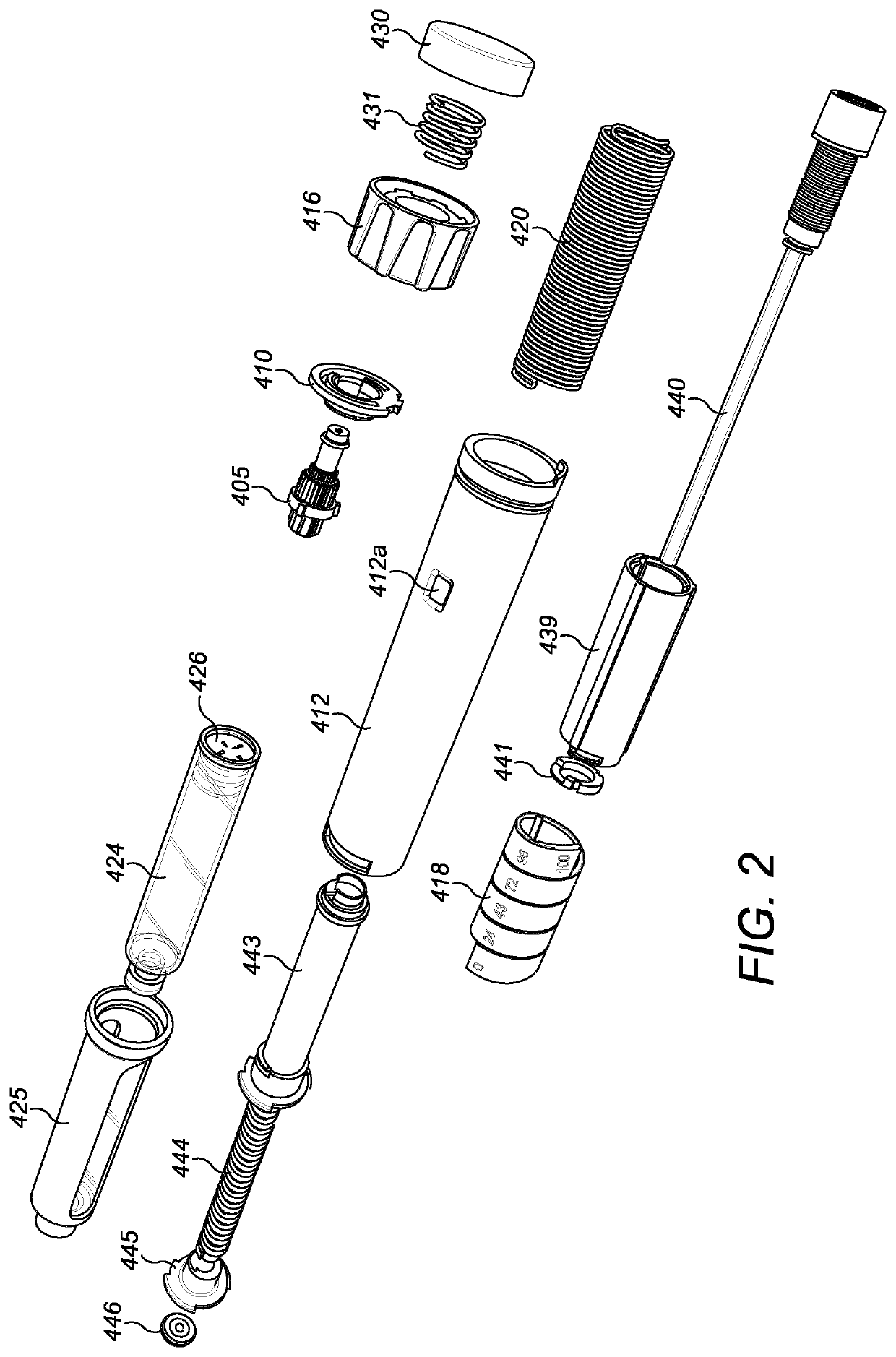
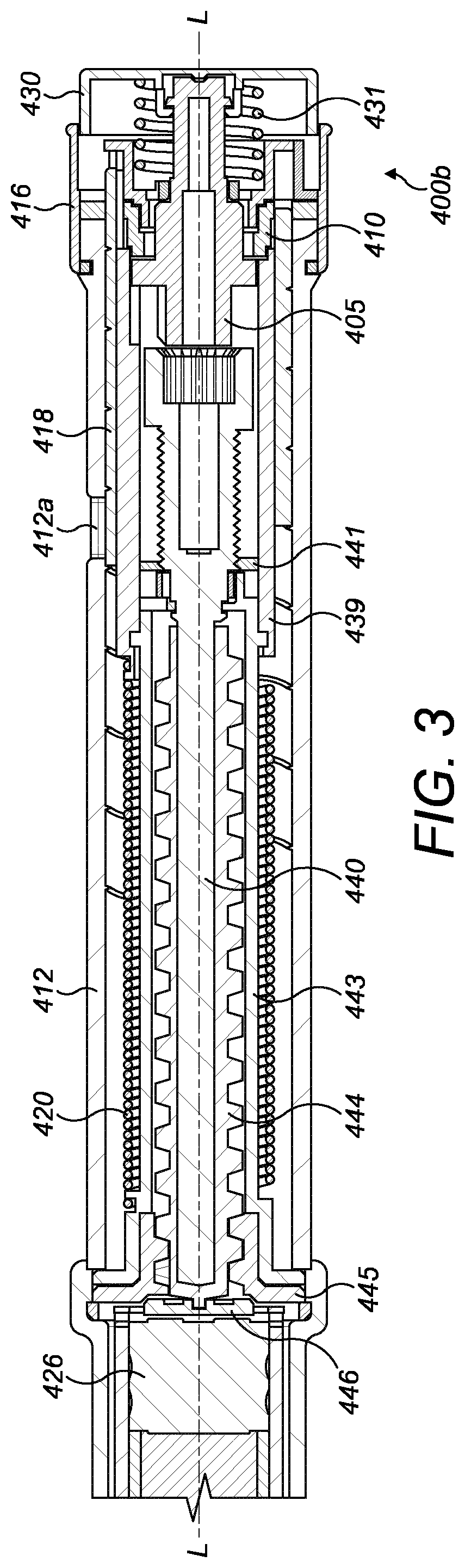
[0097]An injection device 400 according to a non-limiting example embodiment of the present invention is shown in FIGS. 1-3. The injection device 400 is configured to deliver a dose of medicament and extends along a longitudinal axis L between a front end 400a and a rear end 400b of the injection device 400. The injection device 400 has a housing 412 and is able to receive a needle (not shown) at the front end 400a. A dose selector 416 is provided at the rear end 400b and is arranged to permit the selection of a desired dose of medicament for delivery through the needle into an injection site. The housing 412 includes an aperture 412a through which a dose indicator, for example a number sleeve 418 is visible.

[0098]A cartridge holder 425 holds a medicament cartridge 424 from which medicament is expelled by the forward axial movement of a cartridge stopper 426. The cartridge stopper 426 is driven axially forward by a drive mechanism described later bel...


PUM


Abstract

An injection device comprises a housing having a longitudinal axis, an axially-depressible dose button (430), a dose indicator (418), a dose setting mechanism operatively coupled to said dose indicator and capable of setting a dose to be ejected from the injection device and spring capable of storing energy necessary for ejecting the dose from the injection device. The spring (420) is coupled to the dose setting mechanism such that a charging force can be transferred from the dose setting mechanism to the spring to increase the energy stored by the spring. The dose setting mechanism comprises an assembly of three components, including: •a ratchet ring (410) rotationally and axially locked with respect to said housing, the ratchet ring including a ratchet component; •a drive plate (405) including a first set of splines forming a ratchet arrangement with said ratchet component; and•a dose selector (416) capable of being rotated about said longitudinal axis with respect to said housing to set the dose and including splines for disengaging said ratchet arrangement. The ratchet component is capable of interacting with both the splines on the dose selector and the splines on the drive plate.

Description

CROSS-REFERENCE TO RELATED APPLICATIONS[0001]This application is the National Stage of International Patent Application No. PCT / EP2017 / 072714, filed Sep. 11, 2017, which claims priority from Great Britain Patent Application No. 1615442.9 filed Sep. 12, 2016, the entire contents of both of which applications are incorporated herein by reference.[0002]This disclosure relates to the field of a dose setting mechanism for an injection device, preferably a reusable pen-type injection device.BACKGROUND[0003]Certain injection devices have a dose setting member, or dose selector, via which the user can select a desired dose of medicament to be delivered from the injection device. The dose selector can commonly be actuated in one direction to increase the set dose (“dialling up”) and actuated in another direction to decrease the set dose (“dialling down”). As the dose is dialled up or down, this correspondingly increases or decreases stored energy in the device (e.g. in a torsion spring). An ...

Claims


Application Information

Patent Timeline
Patent Type & Authority Patents(United States)
IPC IPC(8): A61M5/315A61M5/20A61M5/31
CPCA61M5/31553A61M5/2033A61M5/31541A61M5/31593A61M2005/3126A61M2205/582A61M5/20A61M5/24A61M5/31535A61M5/3157A61M5/31583
Inventor HEWSON, KARL JAMESKOOYMAN, JEREMY JAMES ROBERTCASTRO PELAYO, XORGE
Owner NORTON HEALTHCARE
Why Eureka
Try Eureka