Airbag device with horn switch body

a technology of horn switch and airbag, which is applied in the direction of pedestrian/occupant safety arrangement, vehicle components, electric/fluid circuit, etc., can solve the problems of difficult post-processing and abnormal noise, and achieve the effect of smooth arrangemen

Active Publication Date: 2022-05-24
TOYODA GOSEI CO LTD
View PDF18 Cites 0 Cited by
  • Summary
  • Abstract
  • Description
  • Claims
  • Application Information

AI Technical Summary

Benefits of technology

[0006]The invention solves the problem described above and an object thereof is to provide an airbag device with a horn switch body which can prevent interference with surroundings in a case of the horn switch body that generates abnormal noise with a simple configuration.
[0007]According to an aspect of the invention, there is provided an airbag device with a horn switch body which is configured so as to be installed in an upper surface side in a boss portion near a center of a steering wheel, the airbag device including: an airbag which inflates by receiving inflation gas; an inflator for supplying inflation gas to the airbag; a pad covering the folded airbag; a mounting base made of sheet metal which holds the airbag, the inflator, and the pad; a horn switch body having an assembling pin to be assembled to a main body side of the steering wheel; and a support plate made of a sheet metal which supports the horn switch body as a configuration attached to a lower surface side of the mounting base, wherein: the mounting base and the support plate have an insertion hole for inserting a main body portion for discharging inflation gas in the inflator; a plurality of mutually opposed parts around the insertion hole are respectively set as switch disposition portions which allow a synthetic resin case surrounding the top, bottom, and sides of the contact portion of the horn switch body to be disposed between the mounting base and the support plate; the support plate disposes the switch disposition portion from a lower surface side of the switch disposition portion of the mounting base to a step portion which is recessed by an approximate height of the case, so the case is arranged between an upper surface side of the step portion and a lower surface side of the switch disposition portion in the mounting base; the horn switch body protrudes a lower end side of the assembling pin from inside the case through the support plate and assembles it to a main body side of the steering wheel and places a movable-side contact point of the contact portion on a lower surface side of a ceiling wall portion of the case in the case and places a fixed-side contact point of the contact portion on an upper end side of the assembling pin provided in the case; an upward movement of the case is regulated by an upper end side of the assembling pin and a spring is arranged between a lower surface side of the case and a lower end side of the assembling pin to bias the case and the lower end side of the assembling pin in a direction to separate them; and the case around the assembling pin of the horn switch body, the mounting base of the switch disposition portion, or the support plate is provided with a spacer capable of preventing rattling of the switch disposition portion in the case.

Problems solved by technology

In such a case, due to the gap generated between the case and the mounting base of the switch disposition portion or the support plate while the vehicle equipped with the airbag device is travelling, the case may interfere (abut) with the mounting base or the support plate, which may cause abnormal noise.
That is, when the spacer is integrally formed in the synthetic resin case, it is necessary to provide a molding concave portion for forming a spacer in the molding die of the synthetic resin member where the spacer is to be provided and it is difficult to form the spacer in the case itself by post-processing.
Therefore, even when a long linear bead is arranged, it is difficult to interfere with the mounting seat of the mounting base for attaching the inflator and the airbag around the insertion hole, and thus the bead can be smoothly arranged.

Method used


Image

  • Airbag device with horn switch body
  • Airbag device with horn switch body
  • Airbag device with horn switch body

Examples


Embodiment Construction

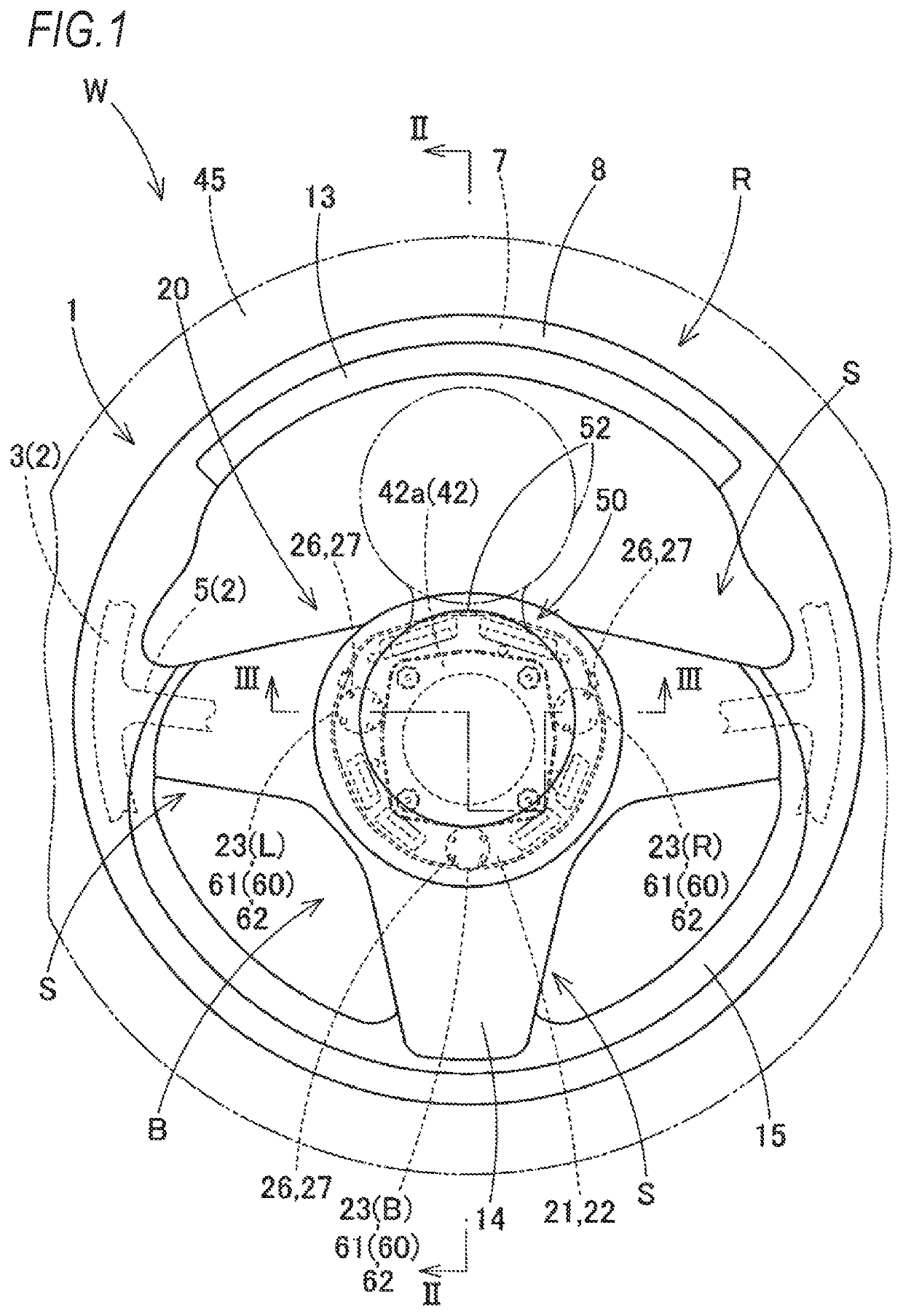
[0040]Hereinafter, when an embodiment of the invention is described with reference to the drawings, as illustrated in FIG. 1, a steering wheel W on which an airbag device 20 of the embodiment is mounted includes a main body (steering wheel main body) 1 of a steering wheel W having a ring portion R gripped at the time of steering, a boss portion B disposed at the center of the ring portion R, and a spoke portion S connecting the ring portion R and the boss portion B and the airbag device 20 disposed above the boss portion B.

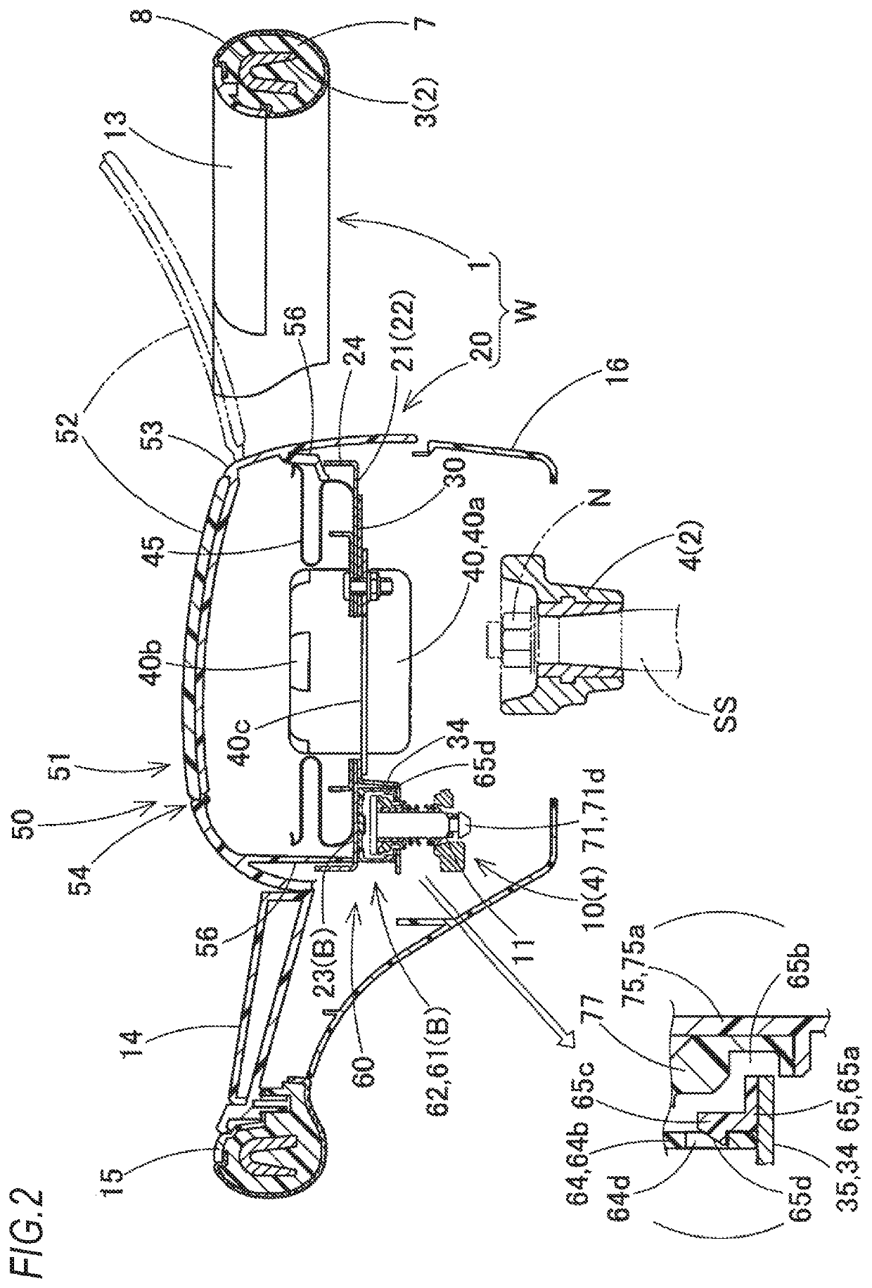
[0041]Regarding the directions of up-down, left-right, and front-back in the present specification, based on the straight steering of a vehicle in a state where the steering wheel W is connected to a steering shaft SS (see FIG. 2) of the vehicle with a nut N fixed thereto, the up-down direction corresponds to a vertical direction along an axial direction of the steering shaft SS and the left-right direction corresponds to a left-right direction of the vehicle in a...


PUM


Abstract

An airbag device with a horn switch body, configured so as to be installed in an upper surface side in a boss portion near a center of a steering wheel, includes: an airbag which inflates by receiving inflation gas; an inflator for supplying inflation gas to the airbag; a pad covering the folded airbag; a mounting base made of sheet metal which holds the airbag, the inflator, and the pad; a horn switch body having an assembling pin to be assembled to a main body side of the steering wheel; and a support plate made of a sheet metal which supports the horn switch body as a configuration attached to a lower surface side of the mounting base. A case around the assembling pin, the mounting base, or the support plate is provided with a spacer capable of preventing rattling of the switch disposition portion in the case.

Description

CROSS-REFERENCE TO RELATED APPLICATION(S)[0001]This application is based upon and claims the benefit of priority from prior Japanese patent application No. 2019-065997 filed on Mar. 29, 2019, and Japanese patent application No. 2019-217034 filed on Nov. 29, 2019, the entire contents of which are incorporated herein by reference.BACKGROUND1. Field of the Invention[0002]The present invention relates to an airbag device with a horn switch body which is attached to a main body of a steering wheel of a vehicle.2. Description of the Related Art[0003]In related art, an airbag device with a horn switch body of this type is configured to be mounted on an upper surface side of a boss portion near a center of a steering wheel. (For example, see JP-A-2016-084005). The airbag device is configured by including an airbag which inflates by receiving inflation gas, an inflator which supplies the inflation gas to the airbag, a pad which covers the folded airbag, a sheet metal mounting base to hold th...

Claims


Application Information

Patent Timeline
Patent Type & Authority Patents(United States)
IPC IPC(8): B60R21/203B60Q5/00B60R21/237
CPCB60R21/2037B60Q5/003B60R21/203B60R21/237B60R21/231B60R21/26B60R16/005B60K37/06
Inventor NAGATA, MATSUOSAKURAI, KOJIKANZAKI, HIROTOSHISUMITA, KENJISAKAMOTO, HIROKINONOYAMA, YUKI
Owner TOYODA GOSEI CO LTD
Why Eureka
Try Eureka