Vibration-damping device

a vibration-damping device and vibration-damping technology, which is applied in the direction of shock absorbers, jet propulsion mountings, transportation and packaging, etc., can solve the problems of generating negative pressure and abnormal noise from cavitation collapse, and achieve stable damping performance, prevent negative pressure generation in the main liquid chamber, and facilitate manufacturing

Active Publication Date: 2018-11-20
PROSPIRA CORP
View PDF27 Cites 0 Cited by
  • Summary
  • Abstract
  • Description
  • Claims
  • Application Information

AI Technical Summary

Benefits of technology

[0010]According to the vibration-damping device related to the present invention, manufacturing can be easily performed due to a simple structure, generation of a negative pressure in the main liquid chamber can be prevented, and a stable damping performance can be exhibited for a prolonged period of time while generation of abnormal noise is reduced.

Problems solved by technology

Then, there is a possibility, for example, that abnormal noise resulting from cavitation collapse caused by generation of a negative pressure may be generated, or a load may be applied to the first attachment member and other components that constitute the other vibration-damping device.

Method used


Image

  • Vibration-damping device
  • Vibration-damping device
  • Vibration-damping device

Examples


first embodiment

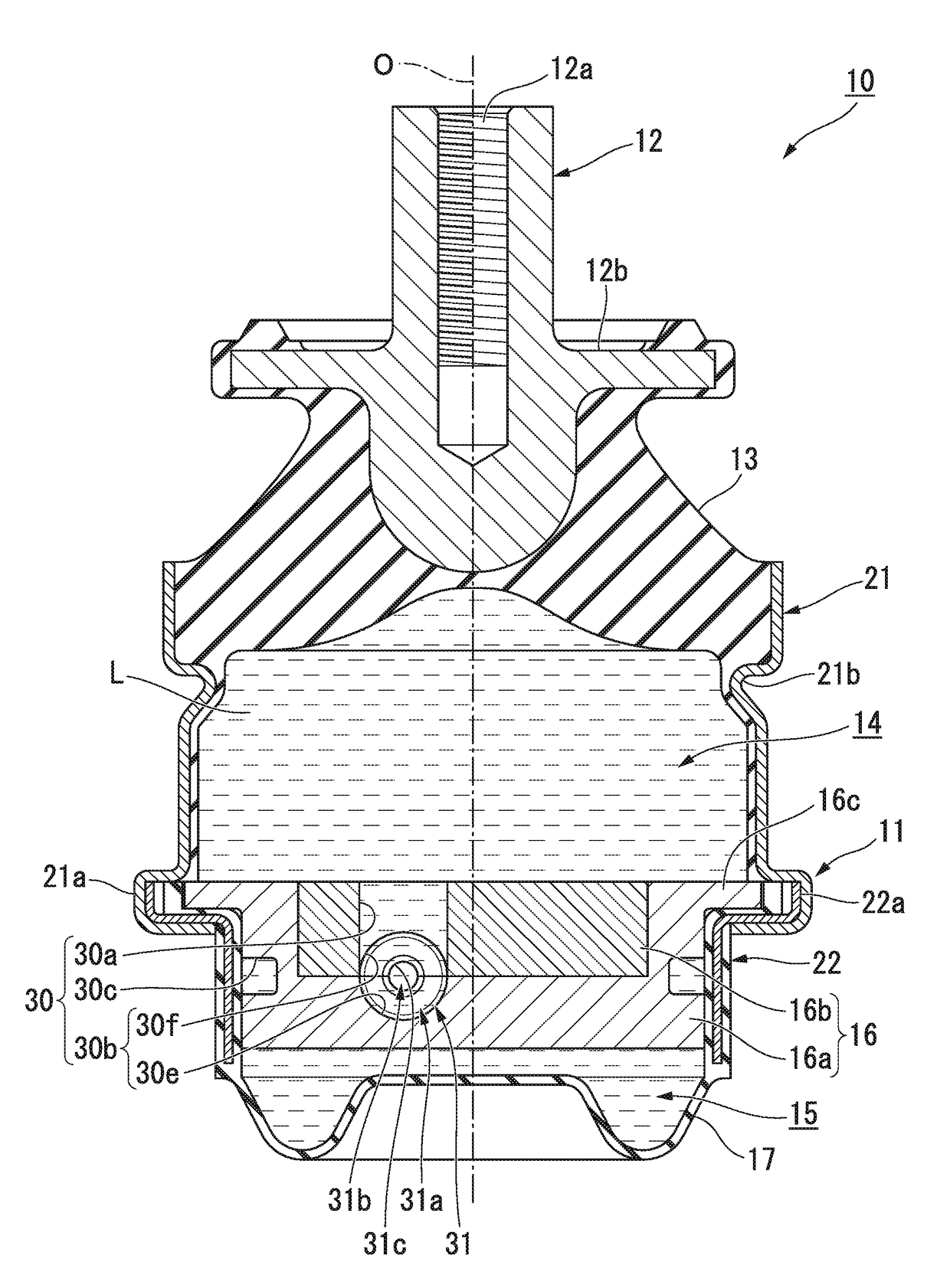
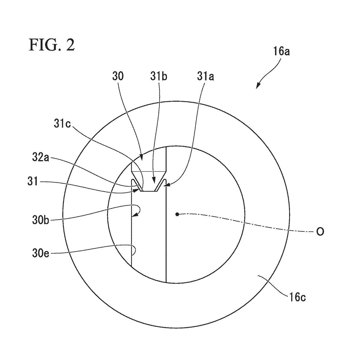
[0026]A first embodiment of a vibration-damping device related to the present invention will be described below, with reference to FIGS. 1 to 7.

[0027]The vibration-damping device 10, as is shown in FIG. 1, includes a tubular first attachment member 11 that is coupled to any one of a vibration generating part and a vibration receiving part, a second attachment member 12 that is coupled to the other thereof, an elastic body 13 that couples the first attachment member 11 and the second attachment member 12 together, and a partitioning member 16 that partitions a liquid chamber within the first attachment member 11 in which a liquid L is enclosed, into a main liquid chamber (first liquid chamber) 14 that has the elastic body 13 in a portion of a wall surface thereof, and an auxiliary liquid chamber (second liquid chamber) 15.

[0028]In FIG. 1, the second attachment member 12 is formed in a pillar shape, the elastic body 13 is formed in a tubular shape, and the first attachment member 11, ...

second embodiment

[0073]Next, a second embodiment of the vibration-damping device related to the present invention will be described with reference to FIGS. 8 and 9.

[0074]In addition, in the second embodiment, the same portions as the constituent elements in the first embodiment will be designated by the same reference signs and a description thereof will be omitted, and only different points will be described.

[0075]In the vibration-damping device of the present embodiment, a flow changing protrusion 36 is formed in a plate shape that protrudes from the inner peripheral surface of the limiting passage 30, instead of being formed in a tubular shape that extends in the flow passage axis M direction. The flow changing protrusion 36 is intermittently disposed over the entire circumference of the flow passage axis M, and a pair of the flow changing protrusions are formed with the flow passage axis M being interposed therebetween in the example shown. The flow changing protrusions 36 are formed with the sa...

third embodiment

[0081]Next, a third embodiment of the vibration-damping device related to the present invention will be described with reference to FIG. 10.

[0082]In the third embodiment, the same portions as the constituent elements in the first embodiment will be designated by the same reference signs and a description thereof will be omitted, and only different points will be described.

[0083]In the vibration-damping device of the present embodiment, a flow changing protrusion 41 is formed in an annular shape that is open on the flow passage axis M direction, instead of being formed in a tubular shape that extends in the flow passage axis M direction. The flow changing protrusion 41 continuously extends over the entire circumference around the flow passage axis M.

[0084]The flow changing protrusion 41 is formed such that the size thereof in the flow passage axis M direction becomes small from both sides in the flow passage axis M direction gradually from the base end toward the protruding end, assu...


PUM


Abstract

A vibration-damping device (10) includes a first attachment member (11), a second attachment member (12), an elastic body, and a partitioning member (16). A limiting passage (30) that allows a main liquid chamber (14) and an auxiliary liquid chamber (15) to communicate with each other is formed in the partitioning member (16). An inner peripheral surface of the limiting passage (30) is provided with a flow changing protrusion (31) that protrudes toward an inner side in a radial direction of the limiting passage (30) and that changes the flow of a liquid (L) that flows into the limiting passage (30) from the main liquid chamber (14) and flows through the limiting passage (30) in an axial direction of the limiting passage (30). In a vertical cross-sectional view passing through an axis of the limiting passage (30) and through the flow changing protrusion (31), the limiting passage (30) and the flow changing protrusion (31) have symmetrical shapes with respect to the axis. A protruding end of the flow changing protrusion (31) forms an inner peripheral edge of a passage hole (31c) that is open on both sides in the axial direction.

Description

TECHNICAL FIELD[0001]The present invention relates to a vibration-damping device that is applied to, for example, automobiles, industrial machines, or the like, and absorbs and damps vibrations of vibration generating parts, such as engines.[0002]Priority is claimed on Japanese Patent Application No. 2014-094160, filed on Apr. 30, 2014, the content of which is incorporated herein by reference.BACKGROUND ART[0003]For this type vibration-damping device, conventionally, a configuration including a tubular first attachment member that is coupled to any one of a vibration generating part and a vibration receiving part, a second attachment member that is coupled to the other thereof, an elastic body that couples the first attachment member and the second attachment member together, and a partitioning member that partitions a liquid chamber within the first attachment member having a liquid enclosed therein into a main liquid chamber having the elastic body as a portion of a wall surface t...

Claims


Application Information

Patent Timeline
Patent Type & Authority Patents(United States)
IPC IPC(8): F16F5/00F16F13/10B60K5/12F16F13/14
CPCF16F13/107F16F13/14F16F13/10B60K5/1208
Inventor UEKI, AKIRA
Owner PROSPIRA CORP
Why Eureka
Try Eureka