Vehicle understructure

a technology for understructures and vehicles, applied in the field of understructures of vehicles, can solve the problems of undercover hole formation, road surface interference, and high fastening force of fastening parts, and achieve the effect of keeping the fastening force in the fastening part high

Active Publication Date: 2019-02-05
TOYOTA JIDOSHA KK
View PDF18 Cites 0 Cited by
  • Summary
  • Abstract
  • Description
  • Claims
  • Application Information

AI Technical Summary

Benefits of technology

[0010]The disclosure provides a vehicle understructure that can suppress the problems caused by a road surface interfering with an undercover.
[0012]By virtue of the specific matter, the interference part, which is a portion of the undercover and that faces the fastening part (a fastening part that interferes with the undercover that is displaced upward when the road surface interferes with the undercover) of the transaxle, is reinforced by the metal plate. Therefore, hole formation of the undercover when the road surface interferes with the undercover (hole formation resulting from the undercover being caught between the fastening part of the transaxle and the road surface) is suppressed. Otherwise, even when hole formation occurs in the undercover, the metal plate restrains the road surface from directly interfering with the fastening part (restrains the road surface from rubbing against the fastening part). For this reason, there is no case where the fastening part is scraped due to direct interference of the road surface with the fastening part of the transaxle (there is no case where the fastening part is scraped as the road surface rubs against the fastening part). As a result, a fastening force in the fastening part can be kept high.
[0014]According to the above description, even in a case where the undercover is displaced upward due to a road surface interference, the sound absorbing material or shock absorbing material is interposed between the transaxle and the metal plate. That is, according to the above, the transaxle and the metal plate do not come into direct contact with each other, and generation of abnormal noise resulting from the contact between metals can be suppressed.
[0016]During vehicle traveling, the fastening part located on the lowest side when the transaxle rocks downward about the supporting position of the mount member, and the undercover approach each other. At the time of a road surface interference, a possibility that the undercover is caught between the fastening part and the road surface and hole formation occurs in the undercover is high. In the aspect of the disclosure, the interference part of the undercover with a high possibility that the hole formation occurs is reinforced by the metal plate. Therefore, even when the undercover is caught, the hole formation of the undercover is suppressed, or even when the hole formation occurs in the undercover, the metal plate restrains the road surface from directly interfering with the fastening part. For this reason, there is no case where the fastening part is scraped due to direct interference of the road surface with the fastening part of the transaxle. As a result, a fastening force in the fastening part can be kept high.
[0018]The lower end of the second flange of the housing located on the case body side is located nearer to the lower side than the lower end of the first flange of the housing located on the internal combustion engine side. Accordingly, a work space in the fastening work between the housing and the case body is secured on the housing side (nearer to the housing than the case body). That is, fastening work (bolt fastening work or the like) using a tool is performed toward the case body from the housing side. In a case where the lower end of the second flange of the housing located on the case body side is located nearer to the lower side than the lower end of the first flange of the housing located on the internal combustion engine side in consideration of workability as described above, at the time of a road surface interference, there is a high possibility that the undercover is caught in the road surface and the fastening part on the lower side of the fastening part between the second flange of the housing located on the case body side and the third flange of the case body, and hole formation occurs in the undercover. In the aspect of the disclosure, the interference part of the undercover, with a high possibility that the hole formation occurs, is reinforced by the metal plate. Therefore, even when the undercover is caught, the hole formation of the undercover is suppressed, or even when the hole formation occurs in the undercover, the metal plate restrains the road surface from directly interfering with the fastening part. For this reason, there is no case where the fastening part is scraped due to direct interference of the road surface with the fastening part of the transaxle. As a result, a fastening force in the fastening part can be kept high.
[0019]In the aspect of the disclosure, in the undercover, a portion including the interference part that faces the fastening part (the fastening part that interferes with the undercover displaced upward when the road surface interferes with the undercover) of the transaxle is partially reinforced by the metal plate. For this reason, hole formation of the undercover when the road surface interferes with the undercover is suppressed. Otherwise, even when hole formation occurs in the undercover, the metal plate restrains the road surface from directly interfering with the fastening part. Therefore, there is no case where the fastening part is scraped due to direct interference of the road surface with the fastening part of the transaxle. As a result, a fastening force in the fastening part can be kept high.

Problems solved by technology

Therefore, in a case where irregularities are present on a road surface, the road surface may interfere with an undercover (road surface interference).
However, in a case where the undercover is made of resin, there is a possibility that hole formation occurs in the undercover due to the road surface interference during vehicle traveling.
Specifically, as the protrusion of the road surface abuts against the lower surface of the undercover to push up the undercover, there is a possibility that the undercover is caught between the lower surface of the transaxle and the road surface (the protrusion of the road surface), the undercover is damaged, and hole formation occurs.
In a case where the hole formation as described above occurs, the protrusion of the road surface directly interferes with the transaxle via the hole during vehicle traveling.
Particularly, since the transaxle includes a plurality of enclosures and flange parts of the enclosures are fastened together by bolting, there is a possibility that the road surface directly interferes with the transaxle via the hole at a fastening part located at a lower part of the transaxle.
In this case, in a case where a situation occurs in which a flange part is scraped due to the road surface interference (the flange part is scraped when the road surface rubs against the flange part) and the road surface interferes with a head part of a bolt of the fastening part, there is a possibility that a fastening force of the bolt decreases.
At the time of a road surface interference, a possibility that the undercover is caught between the fastening part and the road surface and hole formation occurs in the undercover is high.
In a case where the lower end of the second flange of the housing located on the case body side is located nearer to the lower side than the lower end of the first flange of the housing located on the internal combustion engine side in consideration of workability as described above, at the time of a road surface interference, there is a high possibility that the undercover is caught in the road surface and the fastening part on the lower side of the fastening part between the second flange of the housing located on the case body side and the third flange of the case body, and hole formation occurs in the undercover.

Method used


Image

  • Vehicle understructure
  • Vehicle understructure
  • Vehicle understructure

Examples


first embodiment

[0028

[0029]Schematic Structure of Powertrain Unit

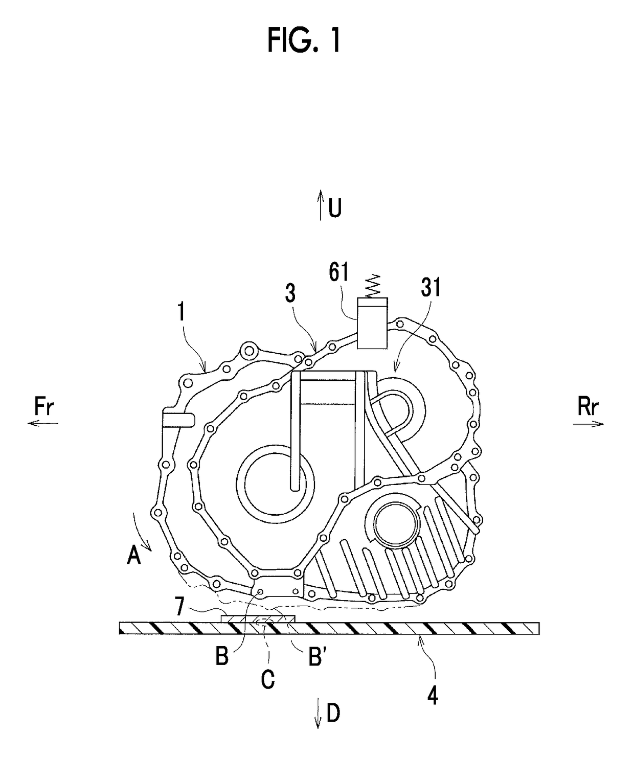
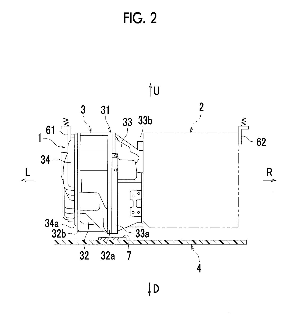
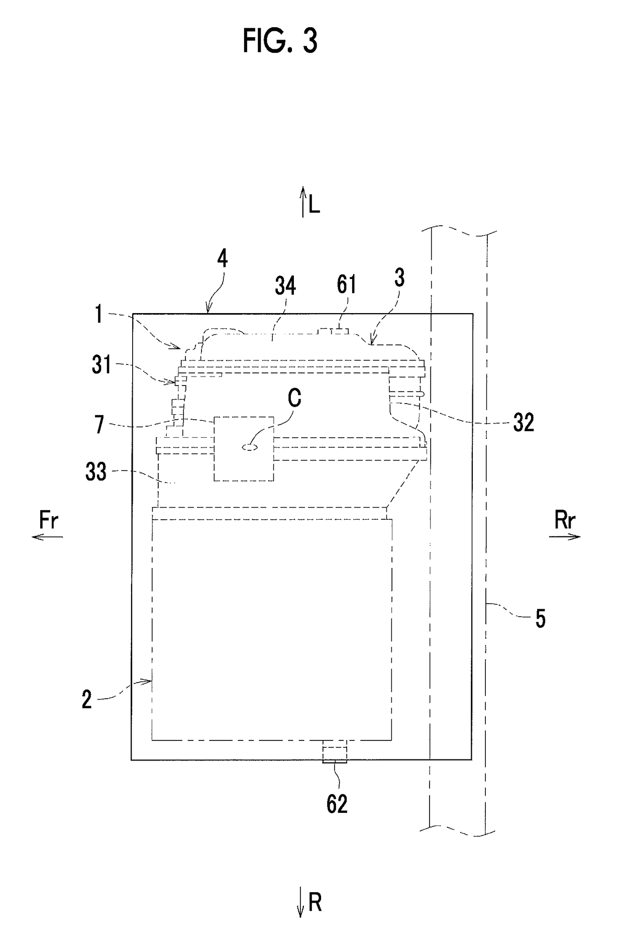
[0030]FIG. 1 is a side view illustrating an arrangement layout of a powertrain unit 1 and an undercover 4 related to the present embodiment. FIG. 2 is a back view (a view viewed from the rear of a vehicle) illustrating the arrangement layout of the powertrain unit 1 and the undercover 4. FIG. 3 is a bottom view illustrating the arrangement layout of the powertrain unit 1 and the undercover 4. In FIGS. 1 to 3, arrow Fr indicates the front of the vehicle, arrow Rr indicates the rear of the vehicle, arrow U indicates upward, arrow D indicates downward, arrow R indicates the right side of the vehicle, and arrow L indicates the left side of the vehicle.

[0031]As illustrated in FIGS. 1 to 3, the powertrain unit 1 has a structure into which an engine 2 (refer to an imaginary line of FIG. 2), a transaxle 3, and the like are integrally incorporated.

[0032]In the transaxle 3, a damper, a planetary gear, a power generating motor, a traveling drive...

second embodiment

[0052

[0053]A second embodiment will be described. Here, solely differences from the first embodiment will be described.

[0054]FIG. 4 is a side view illustrating an arrangement layout of the powertrain unit 1 and the undercover 4 in the present embodiment. As illustrated in FIG. 4, the undercover 4 in the present embodiment has a structure in which a shock absorbing material 8 made of rubber is further attached to an upper surface of the metal plate 7 attached to the upper surface of the undercover 4. The shape of the shock absorbing material 8 (the shape thereof in a plan view) is the same square shape as that of the metal plate 7. As means for attaching the shock absorbing material 8 to the upper surface of the metal plate 7, a resin clip, riveting, bolting, bonding, or the like is applicable.

[0055]The shape of the shock absorbing material 8 is not limited to the aforementioned shape, and is appropriately set. For example, the shape of the shock absorbing material 8 in a plan view m...

third embodiment

[0057

[0058]A third embodiment will be described. Here, solely differences from the first embodiment will also be described.

[0059]FIG. 5 is a side view illustrating an arrangement layout of the powertrain unit 1 and the undercover 4 in the present embodiment. As illustrated in FIG. 5, in the undercover 4 in the present embodiment, the metal plate 7 is attached to a portion of the lower surface of the undercover 4 and is reinforced. The position where the metal plate 7 is attached is the lower surface of the undercover 4 corresponding to the interference part C that faces the fastening part B of the transaxle 3.

[0060]According to the structure of the present embodiment, the same effects as those in the case of the first embodiment can also be obtained. In the present embodiment, a situation in which the road surface and the interference part C of the undercover 4 come into direct contact with each other can be suppressed with the metal plate 7. Therefore, the effect of restraining the...


PUM


Abstract

A vehicle understructure includes a transaxle including a plurality of enclosures and a fastening part that mutually fastens outer edge parts of the enclosures, an undercover including an interference part that is made of resin, is displaced upward when a road surface interferes with the undercover, and faces the fastening part, and a metal plate that reinforces at least a portion of the interference part.

Description

INCORPORATION BY REFERENCE[0001]The disclosure of Japanese Patent Application No. 2017-055458 filed on Mar. 22, 2017 including the specification, drawings and abstract is incorporated herein by reference in its entirety.BACKGROUND[0002]1. Technical Field[0003]The present disclosure relates to a vehicle understructure. Particularly, the present disclosure relates to improvements in an undercover that covers a lower side of a transaxle.[0004]2. Description of Related Art[0005]In the related art, as disclosed in Japanese Unexamined Patent Application Publication No. 2008-24047 (JP 2008-24047 A), a vehicle understructure in which an undercover is disposed below an engine compartment is known. In the vehicle understructure as described above, in a case where a transaxle is disposed in the engine compartment, the undercover covers a lower side of the transaxle.[0006]Meanwhile, vehicles with a low powertrain arrangement have been developed from the need for a low center of gravity in order...

Claims


Application Information

Patent Timeline
Patent Type & Authority Patents(United States)
IPC IPC(8): B62D25/20B60R13/08B60K5/12B60K17/16
CPCB62D25/2072B60K5/1233B60R13/0838B60R13/0861B60K17/16B60R2013/0807B60R13/0884
Inventor ITO, EIJIIKEDA, AKIHIKO
Owner TOYOTA JIDOSHA KK
Why Eureka
Try Eureka