Shift lever device

a technology of shifting lever and bending load, which is applied in the direction of gearing control, gearing element, belt/chain/gearing, etc., can solve the problems of large shift lever and difficult bending load to be applied to the rod, and achieve the effect of ensuring the durability of the rod

Active Publication Date: 2019-08-13
KK TOKAI RIKA DENKI SEISAKUSHO
View PDF11 Cites 0 Cited by
  • Summary
  • Abstract
  • Description
  • Claims
  • Application Information

AI Technical Summary

Benefits of technology

[0010]The ratio of the amount of lowering of the rod with respect to the amount of rotation of the rotating member is greatest before and after the reference tangent line passes (at a moment the reference tangent line passes) by a position where the reference tangent line, that is at the contact point of the contact surface of the rotating member and the rod, becomes parallel to the reference direction. In accordance with this aspect, the rotation range of the rotating member is set such that the reference tangent line passes the position where the reference tangent line becomes parallel to the reference direction. Therefore, even if the rotation stroke amount of the rotating member is small, the rod stroke amount can effectively be made to be large. Accordingly, a shift lever device, that is suited to making the ratio of the rotation stroke amount of the rotating member with respect to the rod stroke amount be small, can be provided.
[0012]When, partway through the rotation range of the rotating member, the reference tangent line passes by the position where the reference tangent line becomes parallel to the reference direction partway therealong, the direction of the load that is applied from the rotating member to the rod reverses from one side to another side in the reference direction. In accordance with this aspect, load of a directional vector, that runs along the axis of the rotating shaft, can be applied from the rotating member to the rod. Due thereto, before and after the direction of the load that is applied from the rotating member to the rod is reversed, the rod can be moved within the guide hole from one side to the another side in the reference direction, while the rod is slid with respect to the guide hole. Accordingly, before and after the direction of the load that is applied to the rod is reversed, it is difficult for the rod to move away from the guide hole, and the generation of abnormal noise that is due to collision of the rod and the guide hole can be prevented.
[0014]In accordance with this aspect, even when a large load is inputted to the rotating member in a case in which the shift lock mechanism is in the locking state, it is difficult for bending load to be applied to the rod from the contact surface of the rotating member, and it is easy to ensure the durability of the rod.
[0015]In accordance with the disclosure, a shift lever device, that is suited to making the ratio of a rotation stroke amount of a rotating member with respect to a rod stroke amount be small, can be provided.

Problems solved by technology

If the rotation stroke amount of the shift button that is needed in order to obtain a given rod stroke amount is large, a large space is needed in order to permit operation of the shift button, and this leads to the shift lever becoming large.
In accordance with this aspect, even when a large load is inputted to the rotating member in a case in which the shift lock mechanism is in the locking state, it is difficult for bending load to be applied to the rod from the contact surface of the rotating member, and it is easy to ensure the durability of the rod.

Method used


Image

  • Shift lever device
  • Shift lever device
  • Shift lever device

Examples


Embodiment Construction

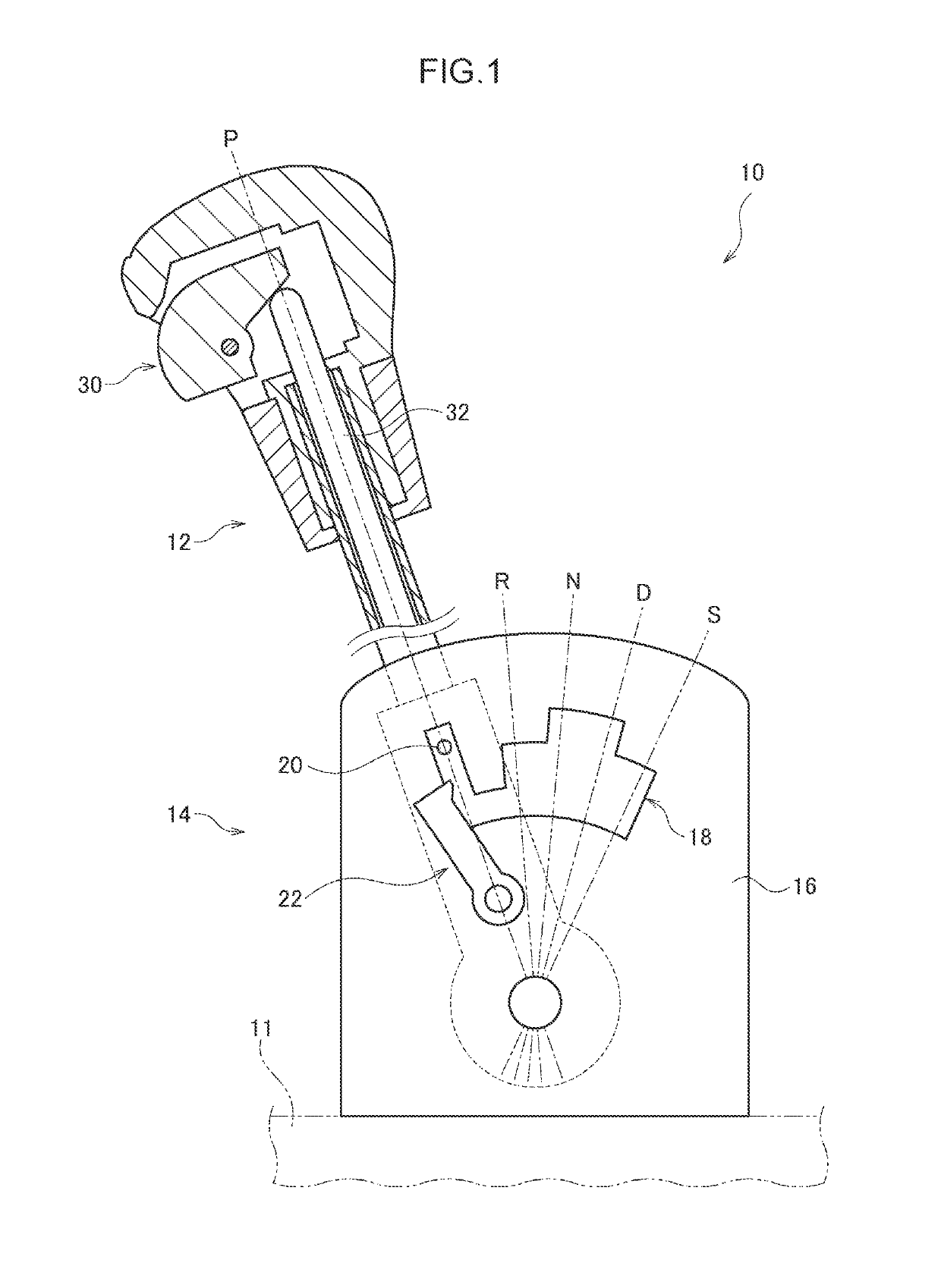
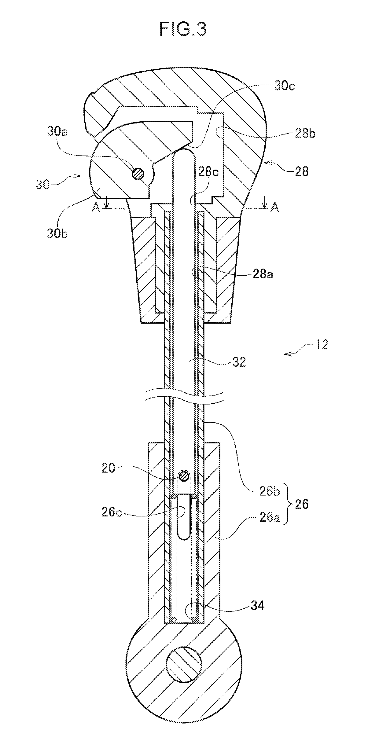
[0027]FIG. 1 is a side view showing a shift lever device 10 of the present exemplary embodiment. This drawing is also a drawing in which the shift lever device 10 is seen from the left side in the vehicle transverse direction. This drawing also shows the internal structure of a portion of a shift lever 12 of the shift lever device 10.

[0028]The shift lever device 10 of the present exemplary embodiment has the shift lever 12 that is supported so as to be rotatable with respect to a base 11. The shift lever 12 is set, for example, at a console that is positioned between a driver's seat and a front passenger's seat. The base 11 is, for example, the floor panel of the vehicle cabin.

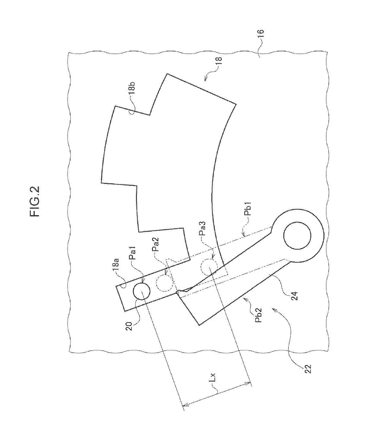
[0029]The shift lever device 10 has a detent mechanism 14 for restricting the rotation of the shift lever 12. The detent mechanism 14 has a detent plate 16 that is disposed at the side of the locus of rotation of the shift lever 12, a detent window (opening) 18 that is formed in the detent plate 16, and a dete...


PUM


Abstract

A shift lever device includes: a lever main-body; a hollow knob provided at a lever main-body distal end portion; a shift-button rotatably mounted to the knob; and a rod that is inserted-through interior of the lever main-body. The shift-button has a contact surface extending in direction of being away from a rotating-shaft of the shift-button, and that, when the shift-button rotates with respect to the knob, contacts an upper end portion of the rod and lowers the rod. Given that direction orthogonal to axial-direction of the rotating-shaft on plane orthogonal to axis of the rod is reference-direction, and that, among tangent-lines at contact points of the contact surface and the rod, tangent-line on plane orthogonal to the rotating-shaft is reference tangent-line, rotation range of the shift-button is set such that, partway through rotation, the reference tangent-line passes position at which the reference tangent-line becomes parallel to the reference-direction.

Description

CROSS-REFERENCE TO RELATED APPLICATION[0001]This application claims priority under 35 USC 119 from Japanese Patent Application No. 2015-253008 filed Dec. 25, 2015, the disclosure of which is incorporated by reference herein.BACKGROUND[0002]Technical Field[0003]The present invention relates to a shift lever device for operating an automatic transmission of a vehicle.[0004]Related Art[0005]There are shift lever devices having a shift lever that is rotated by the driver and a detent mechanism for restricting the rotation of the shift lever. At the shift lever, a shift button is mounted to a knob that the driver grasps, and the rotation restriction by the detent mechanism is canceled interlockingly with operation of the shift button. The driving mode of the automatic transmission is switched due to, in the state in which the driver operates the shift button this way, the driver rotating the shift lever and placing the shift lever at a predetermined range.[0006]Japanese Patent Applicatio...

Claims


Application Information

Patent Timeline
Patent Type & Authority Patents(United States)
IPC IPC(8): F16H61/22F16H59/02F16H59/10
CPCF16H61/22F16H59/10F16H59/0278F16H2059/0282
Inventor KATO, SHORISHIMIZU, ETSUOKITAHARA, TAKAYOSHIMIZUNO, HIRONORIKATO, SABUROFUKUSHIMA, TAKAAKIITO, HIDEAKIMASUDA, TAKAYOSHI
Owner KK TOKAI RIKA DENKI SEISAKUSHO
Why Eureka
Try Eureka