Extensible telescoping mast assembly and deployment mechanism

a telescoping mast and assembly technology, applied in the direction of collapsible antenna means, machine supports, rod connections, etc., can solve the problems of limited dimensional stability and deployed stiffness of the mast, particularly problematic limits on deployed stiffness, and limitations on dimensional stability. achieve the effect of facilitating the latch and facilitating the mast transition

Active Publication Date: 2022-05-24
EAGLE TECH LLC
View PDF21 Cites 0 Cited by
  • Summary
  • Abstract
  • Description
  • Claims
  • Application Information

AI Technical Summary

Benefits of technology

[0005]This document concerns an extensible mast comprised of a plurality of mast sections which are coaxially aligned along a mast axis. Each mast section is formed of an elongated tubular member defined by a sidewall and disposed in a nested configuration with respect to others of the plurality of mast sections when the mast is in a stowed condition. Each mast section is configured to slide along a direction aligned with the mast axis. This sliding action facilitates a transition of the mast from the stowed condition to a deployed condition. In the deployed condition, adjacent mast sections are disposed substantially end to end so as to form a mast having an elongated length extending from a mast base to a mast tip. Each of the mast sections includes one or more latches. These latches are each formed from a portion of the sidewall that is configured to resiliently deflect to facilitate engagement of the latch with a portion of an adjacent mast section. The latches are configured to automatically secure a base end of each of the mast sections to a tip end of an adjacent mast section when the mast is transitioned to the deployed condition.
[0008]If an SEM is used, the plurality of mast sections may each comprise one or more battens through which the SEM extends. Each of these battens can be a structural member which is fixed to the mast section and disposed transverse to the mast axis. The batten will include an aperture of a predetermined shape corresponding to a cross-sectional shape of the SEM when deployed. The battens are advantageous insofar as they can help minimize the potential for buckling of the SEM.
[0010]The solution described herein also concerns a method for deploying an extensible mast. The method can involve arranging a plurality of mast sections coaxially in alignment along a mast axis. Each mast section can comprise an elongated tubular member defined by a sidewall. The method can further involve disposing the plurality of mast sections in a nested configuration with respect to others of the plurality of mast sections when the mast is in a stowed condition. Thereafter, a drive system is used to urge each mast section to slide along a direction aligned with the mast axis. This operation facilitate a transition of the mast from the stowed condition to a deployed condition in which adjacent ones of the mast sections are disposed substantially end to end. Consequently, operation of the drive system will cause the plurality of mast sections to form a mast having an elongated length extending from a mast base to a mast tip. The method can continue with the actions which involve retaining the plurality of mast sections in the deployed condition. This function can involve using one or more latches, each of which is formed from a portion of the sidewall. The latches are configured to resiliently deflect to facilitate engagement of the latch with a portion of an adjacent mast section. The latches operate to automatically secure a base end of each of the mast sections to a tip end of an adjacent mast section when the mast is transitioned to the deployed condition.

Problems solved by technology

But SEMs are limited with regard to the degree of dimensional stability and deployed stiffness that they can provide.
The limitations with respect to dimensional stability can be caused by thermo-elastic distortion and / or thermally accelerated creep.
The limits on deployed stiffness can be particularly problematic with regard to pointing accuracy in the case of reflector antennas.

Method used


Image

  • Extensible telescoping mast assembly and deployment mechanism
  • Extensible telescoping mast assembly and deployment mechanism
  • Extensible telescoping mast assembly and deployment mechanism

Examples


Embodiment Construction

[0025]It will be readily understood that the solution described herein and illustrated in the appended figures could involve a wide variety of different configurations. Thus, the following more detailed description, as represented in the figures, is not intended to limit the scope of the present disclosure, but is merely representative of certain implementations in various different scenarios. While the various aspects are presented in the drawings, the drawings are not necessarily drawn to scale unless specifically indicated.

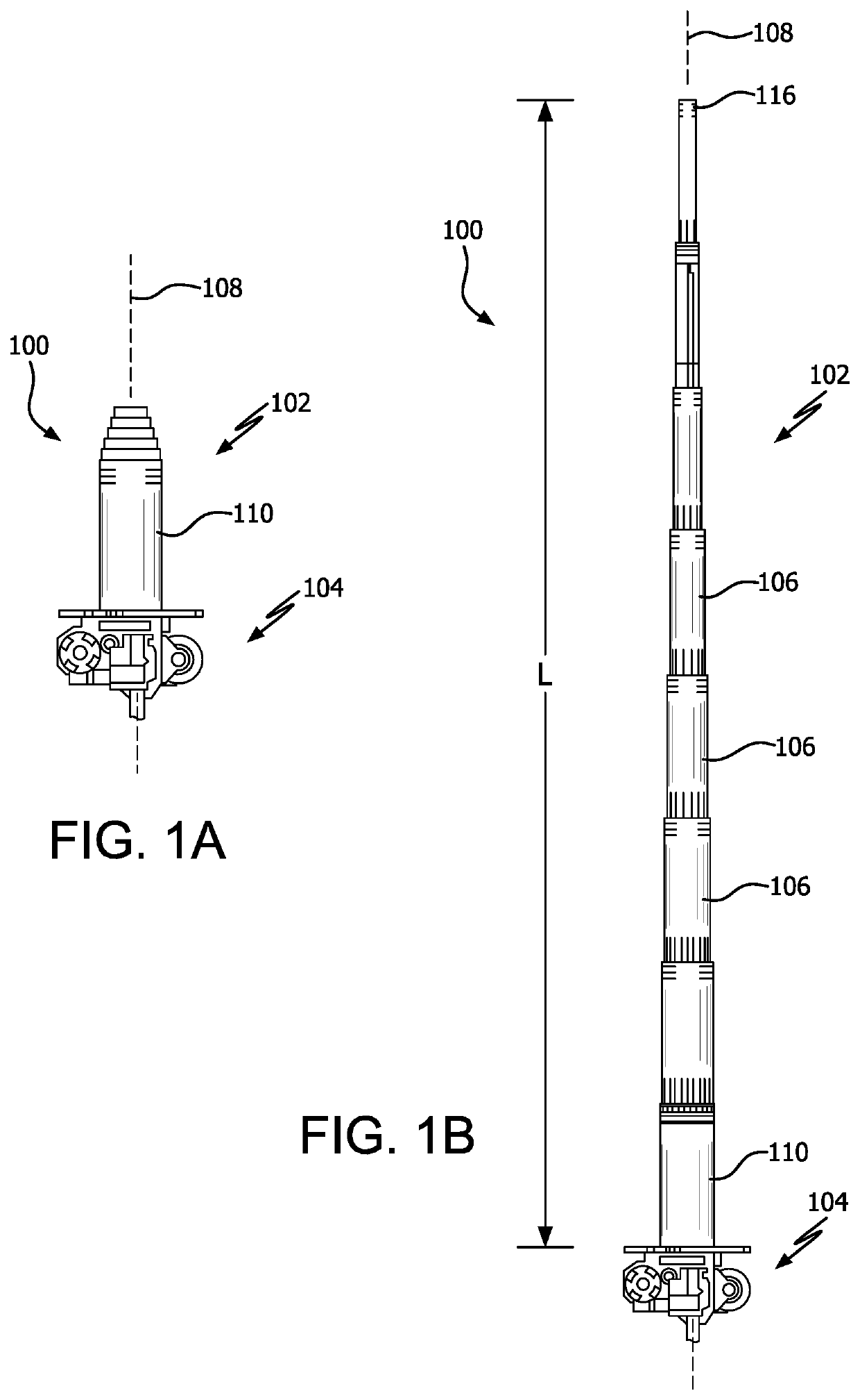
[0026]Extendable masts are needed for a variety of applications, including deployable antenna systems for use on spacecraft. In some scenarios, the extendable masts can serve as booms for supporting antennas and / or various other equipment relating to a particular spacecraft mission. In other scenarios, deployable masts can comprise a part of a deployable reflector for directing radio frequency energy into a desired pattern.

[0027]One conventional type of reflect...


PUM


Abstract

Extensible mast is comprised of multiple mast sections which are aligned along a mast axis. Each mast section is formed of an elongated tubular member disposed in a nested configuration when the mast is in a stowed condition. Each mast section is configured to slide along a direction aligned with the mast axis to facilitate a transition of the mast from the stowed condition to a deployed condition. In the deployed condition, adjacent mast sections are disposed substantially end to end so as to form a mast having an elongated length extending from a mast base to a mast tip. Mast sections includes one or more latches formed from a portion of the sidewall and resiliently engage a portion of an adjacent mast section.

Description

BACKGROUNDStatement of the Technical Field[0001]The technical field of this disclosure concerns extensible telescoping masts, and more particularly methods and systems for deploying same.Description of the Related Art[0002]The related art concerns methods and systems for high precision extensible telescoping masts and associated deployment mechanisms. Compact, low mass, extendable compressive structural members are needed for certain types of tension based deployable systems. For example, such masts can be employed to facilitate deployable antenna reflectors. Similarly, extendable booms are commonly needed in many space-based application to function as satellite offsets and / or deployed compressive members.[0003]One type of deployable compressive structural member is a telescoping mast. Telescoping masts offer commonly comprise a plurality of tapered sections which are stowed coaxially in a nested configuration. The sections deploy by sliding in the axial direction so that individual...

Claims


Application Information

Patent Timeline
Patent Type & Authority Patents(United States)
IPC IPC(8): F16B7/10H01Q1/10F16M11/04F16M11/18H01Q1/12
CPCF16B7/10H01Q1/103F16M11/046F16M11/18H01Q1/1235H01Q15/161H01Q1/288F16B7/105E04H12/182
Inventor MOODY, BRIAN A.MONNIER ROSENNIER, DANASZEKELY, KEVINTOLEDO, GUSTAVO A.KAPPLES, SHAUNWHITNEY, RYAN
Owner EAGLE TECH LLC
Why Eureka
Try Eureka