Eureka AIR delivers breakthrough ideas for toughest innovation challenges, trusted by R&D personnel around the world.

Device and method for setting a connection element on a workpiece

a technology of connecting elements and workpieces, applied in metal-working equipment, metal-working equipment, manufacturing tools, etc., can solve the problems of tension between components and difficult access to fastening points, and achieve the effect of simple and reliable setting of connecting elements

Active Publication Date: 2022-05-31
RICHARD BERGNER VERBINDUNGSTECHN
View PDF14 Cites 0 Cited by
  • Summary
  • Abstract
  • Description
  • Claims
  • Application Information

AI Technical Summary

Benefits of technology

[0010]It is therefore an object of the invention to enable simple and reliable setting of connecting elements, in particular press-in bolts.
[0020]The feed movements of the punch and the embossing sleeve are preferably coordinated with one another in such a way that the collar is at least partially deep-drawn by means of the embossing sleeve and the punching operation with the punch only begins subsequently. In particular, the deep-drawing process is not yet complete when the punching process begins. Alternatively, the embossing sleeve first moves to a front end position before the punching process begins, that is to say before the punch penetrates the workpiece and punches out the hole. This process with the at least partial deep drawing of the collar ensures an accurate, dimensionally accurate hole formation. Alternatively, there is also the possibility of first performing the stamping process and then the deep-drawing process.
[0026]For a reliable absorption of the forces, the embossing sleeve is preferably moved against a second mechanical fixed stop in the retracted position.

Problems solved by technology

In the case of motor vehicles in particular, the connecting elements are often arranged on complex body components, the fastening points being difficult to access for the setting unit due to the complex component geometry.
The disadvantages of conventional systems are as follows: an additional step is required to insert the deep-drawn collar and the punched hole; and by deviating the actual position of the centering pin and the hole or tool position (determined by robot) when “threading” there is tension between the components.
If the deviation is too large, the component cannot be “threaded” onto the centering mandrel, or only with difficulty, which can lead to faults.

Method used


Image

  • Device and method for setting a connection element on a workpiece
  • Device and method for setting a connection element on a workpiece
  • Device and method for setting a connection element on a workpiece

Examples


Embodiment Construction

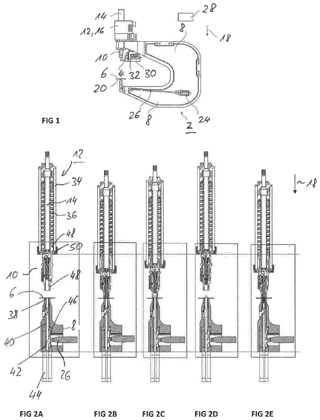
[0050]FIG. 1 shows a device 2 which is designed to carry out a setting process and to set a connecting element 4, in particular a press-in bolt, in a component or workpiece 6. The workpiece 6 is, for example, a sheet metal or sheet metal component, for example a motor vehicle component. The connecting element 4 is in particular a so-called press-in bolt, which is typically connected to the workpiece 6 in a form-fitting and a force-fitting manner. Such a press-in bolt is basically characterized by a head and a shaft adjoining it, for example a threaded shaft.

[0051]The device 2 has a tool carrier 8, which in the exemplary embodiment is designed in the manner of a C-arm. A setting unit 10 is arranged on an upper arch arm, which in turn is connected to a feed unit 12. This has a plunger 14 and a drive 16, in particular an electric motor, which drives the plunger in a feed direction 18.

[0052]Opposite to the setting unit 10 is a component carrier 20 arranged at the lower bow arm of the to...


PUM

PropertyMeasurementUnit
press-in aaaaaaaaaa
press-in forceaaaaaaaaaa
tensionaaaaaaaaaa

Abstract

A device and the method serve to set a connecting element, in particular a press-in bolt, on a workpiece. By means of a setting unit, a hole punching operation for introducing a hole and, at the same time, a hole-forming operation are carried out, in which an edge of the hole is deep-drawn using an embossing sleeve and a collar is formed. In a second stage, the connecting element is pressed in, the punching and hole-forming operation and the pressing taking place within the same axial axis without the workpiece being laterally displaced relative to the device.

Description

[0001]This nonprovisional application is a continuation of International Application No. PCT / EP2018 / 074839, which was filed on Sep. 14, 2018, and which claims priority to German Patent Application No. DE 10 2017 216 348.8, which was filed in Germany on Sep. 14, 2017, and which are both herein incorporated by reference.BACKGROUND OF THE INVENTIONField of the Invention[0002]The present invention relates to a device and a method for carrying out a setting process for setting connecting elements on a workpiece.Description of the Background Art[0003]The connecting elements are, for example, press-in elements such as press-in nuts, press-in bolts (EPB), press-in screws or rivets, which are pressed into a workpiece (component), usually a sheet metal, by exerting a predetermined press-in force. The present application relates in particular to the pressing in of press-in bolts, such as, for example press-in screws. The connecting elements can also be other screws or rivets or bolts. In autom...

Claims


Application Information

Patent Timeline
Patent Type & Authority Patents(United States)
IPC IPC(8): B21J15/28B21J15/02B23P19/06
CPCB21J15/28B21J15/02B23P19/064B21J15/10B21J15/30B21J15/38
Inventor SKOLAUDE, ANDREAS
Owner RICHARD BERGNER VERBINDUNGSTECHN
Why Eureka
Eureka Blog
Learn More