Retrieving a sample of formation fluid in as cased hole

Inactive Publication Date: 2005-04-12
SHELL OIL CO
View PDF26 Cites 23 Cited by
  • Summary
  • Abstract
  • Description
  • Claims
  • Application Information

AI Technical Summary

Benefits of technology

It is an object of the present invention to overcome this drawback and to provide a method to obtain a fluid sample correctly representing the formation fluid.

Problems solved by technology

Unfortunately, the sampled fluid need not always represent the formation fluid.

Method used


Image

  • Retrieving a sample of formation fluid in as cased hole
  • Retrieving a sample of formation fluid in as cased hole
  • Retrieving a sample of formation fluid in as cased hole

Examples


Embodiment Construction

In the specification and the claims the expression a perforation set refers to at least one perforation, wherein, when the set contains two or more perforations, these perforations have the same orientation.

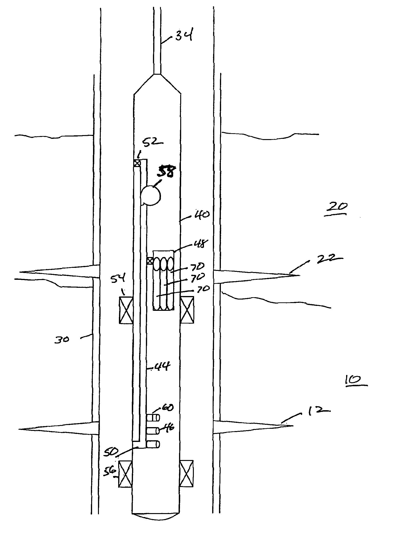
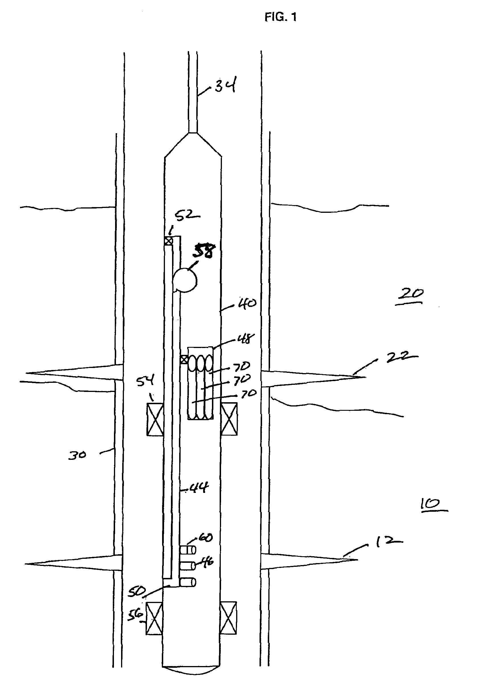
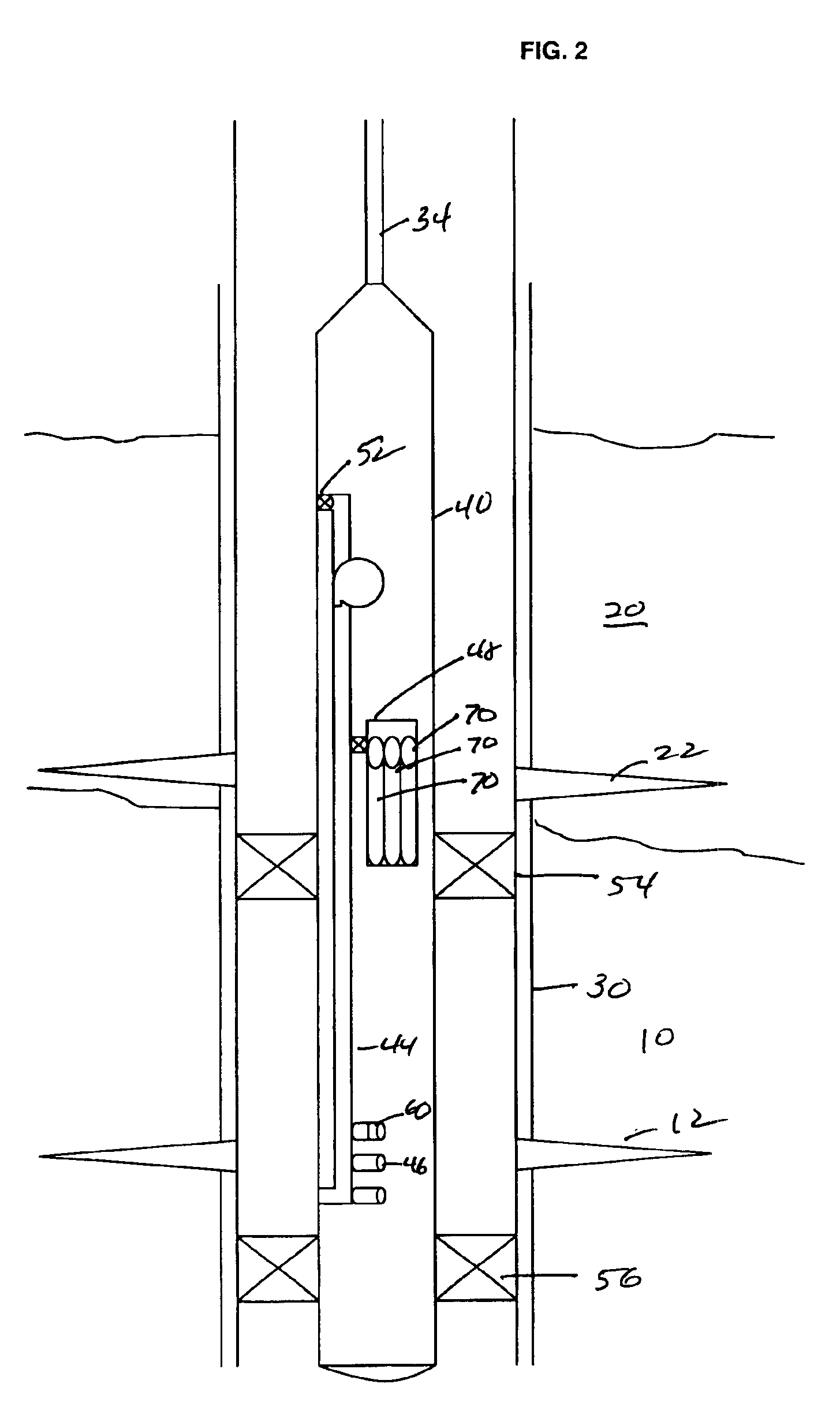
The method of retrieving a sample of formation fluid from a formation layer 20 traversed by a cased borehole according to the invention will now be described in more detail.

With reference to FIG. 1, in order to obtain samples from the formation fluid, first the casing 30 is perforated. The perforations are depicted as 12 and 22 in formation layers 10 and 20 respectively. According to the present invention, perforating the casing 30 involves making a plurality of perforation sets through the casing wall into the formation layer 20. The height of each perforation set 22 is less than the distance between the upper 54 and the lower packer 56 of the sampling tool 40 and the spacing between adjacent perforation sets 12 is at least equal to the length of the longest packer of the sampli...


PUM


Abstract

A method for retrieving a formation fluid sample through a cased borehole utilizing a sampling tool. Sampling tool straddle packers are set about a first set of perforations and annular fluid is drained from the isolated zone, through a central conduit in the tool and discharged above or below the packers. Formation fluid is induced to flow into the central conduit and into sample chambers. The packers are unset, the tool moved to the next set of perforations that are azimuthally offset from the first set of perforations and the sampling process repeated, with subsequent samples being placed in separate sample chambers.

Description

The present application claims priority on European Patent Application 01200178.0, filed on 18 Jan. 2001.FIELD OF THE INVENTIONThe present invention relates to retrieving a sample of formation fluid from a formation layer traversed by a cased borehole. The formation layer is a hydrocarbon-bearing formation layer or a formation layer that is expected to contain hydrocarbons.BACKGROUND OF THE INVENTIONA cased borehole is a borehole lined with a casing that has been cemented in the borehole so that the annulus between the outer surface of the casing and the inner surface of the borehole is filled with set cement. The casing is filled with liquid used to displace the cement out of the casing and into the annulus, before the cement sets. The liquid in the casing is so dense that fluids are prevented from entering into the casing.In order to obtain a sample of the formation fluid from the formation layer, the casing wall is perforated in a predetermined interval within that formation laye...

Claims


Application Information

Patent Timeline
Patent Type & Authority Patents(United States)
IPC IPC(8): E21B49/08E21B49/00
CPCE21B49/081
Inventor HASHEM, MOHAMED NAGUIB
Owner SHELL OIL CO
Why Eureka
Try Eureka