Firearm microstamping and micromarking insert for stamping a firearm identification code and serial number into cartridge shell casings and projectiles

a micro-stamping and insert technology, applied in the direction of ammunition testing, manufacturing tools, instruments, etc., can solve the problems of forensic investigations that are expensive and time-consuming, system purchase and operation at relatively slow production rate,

Inactive Publication Date: 2005-05-03
INDENTIFICATION DYNAMICS
View PDF40 Cites 23 Cited by
  • Summary
  • Abstract
  • Description
  • Claims
  • Application Information

AI Technical Summary

Problems solved by technology

There are currently available a variety of systems for forming a hole, a via, a blind via or some other surface indentation in an exterior surface of an object, but many of these systems are very expensive to purchase and operate at relatively slow production rates.
Currently, such forensic investigations are expensive and time consuming and require personal training and sophisticated equipment that not every law enforcement department has or can afford.
Furthermore, where the used firearm is unavailable,

Method used


Image

  • Firearm microstamping and micromarking insert for stamping a firearm identification code and serial number into cartridge shell casings and projectiles
  • Firearm microstamping and micromarking insert for stamping a firearm identification code and serial number into cartridge shell casings and projectiles
  • Firearm microstamping and micromarking insert for stamping a firearm identification code and serial number into cartridge shell casings and projectiles

Examples


Embodiment Construction

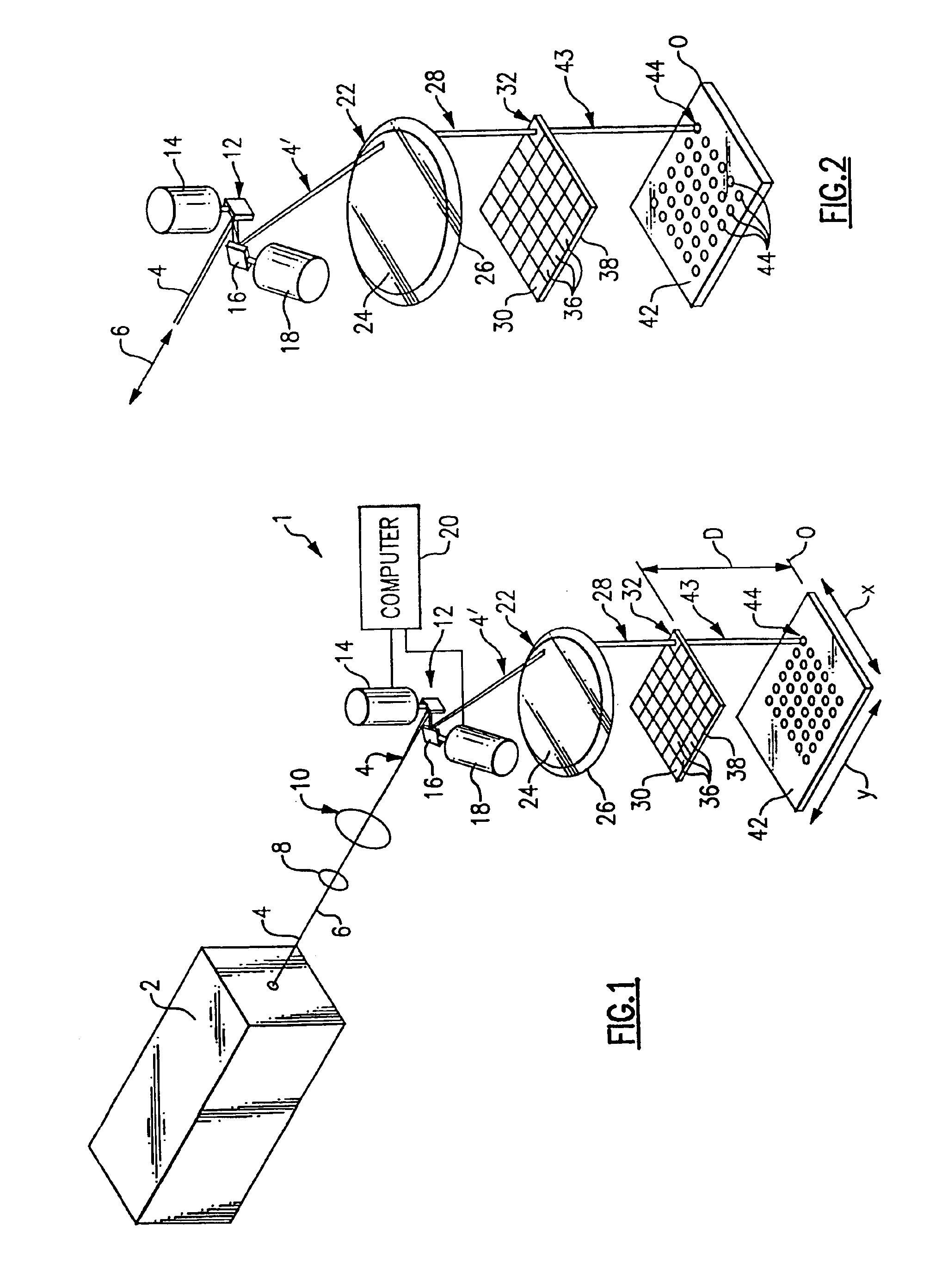
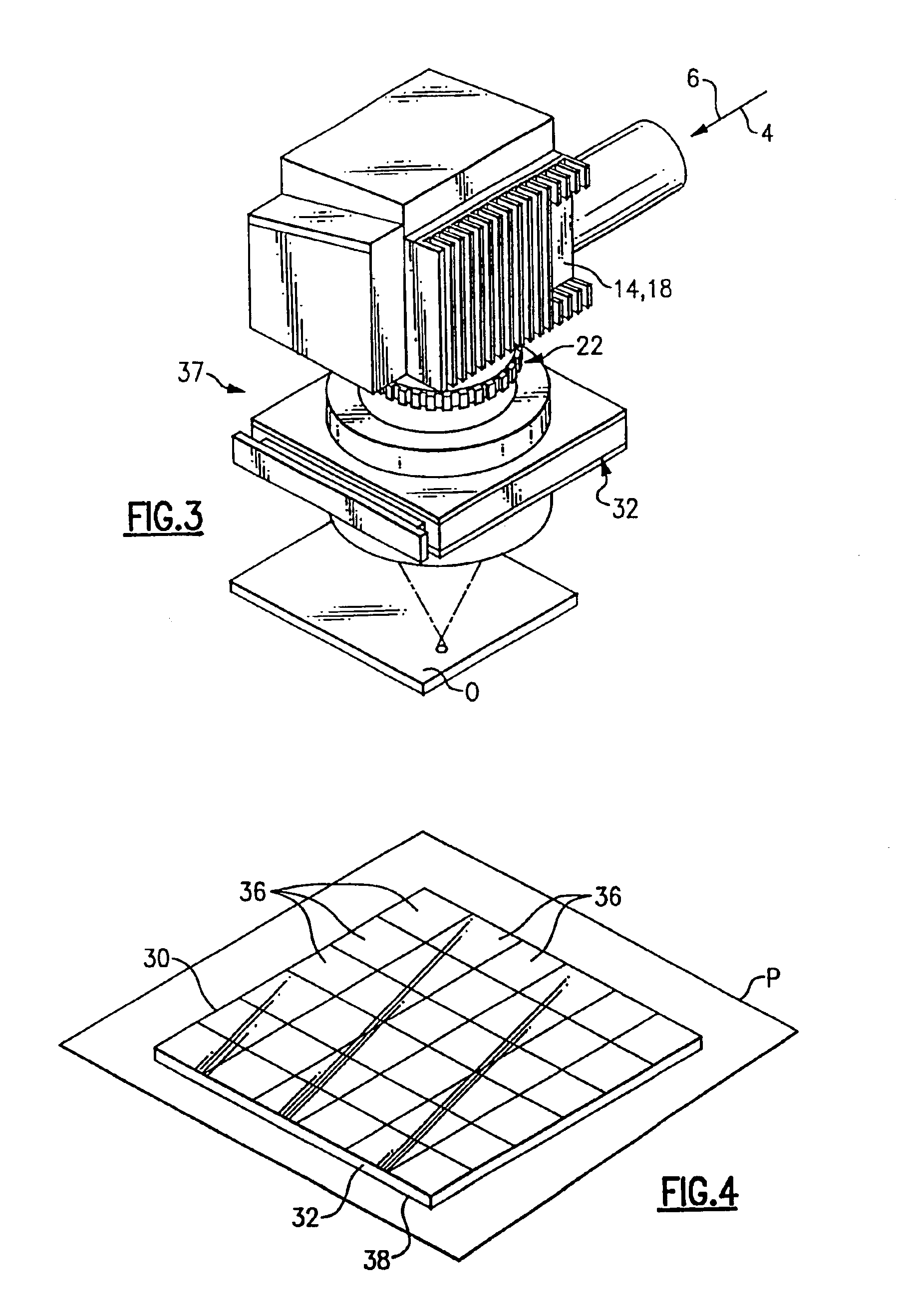
[0050]Turning now to FIGS. 1-4, a detailed description of the imaging system 1 apparatus for ablating high-density array of vias or indentations in a surface of an object, according to the present invention, will now be provided. As can be seen in FIG. 1, a conventional laser 2 (only diagrammatically shown in this Figure) is employed for generating and outputting a laser beam 4. It is to be appreciated that the laser 2 can be either excimer or non-excimer laser and further details and operating parameters for the preferred laser, for use with the present invention, will be provided below. The laser beam 4, generated by the laser 2, is either an ultraviolet, a visible, an infrared, a coherent radiation beam or some other light radiation beam 4 which is supplied along a laser axis 6 toward at least a first expansion telescope or expansion lens 8 and also preferably then supplied to a second expansion telescope or expansion lens 10. The purpose of the expansion telescope or lens 8 and / ...


PUM

PropertyMeasurementUnit
Shapeaaaaaaaaaa

Abstract

A firearm comprising a gun barrel for accommodating a desired round of ammunition having a bullet, a shell casing and a primer. The gun barrel has a firing pin associated with a chamber of the gun barrel and the firing pin is activated by a trigger assembly. When the firing pin is activated by the trigger assembly, a striking surface of the firing pin strikes the primer and discharges the round of ammunition to propel the bullet out of the opposite end of the gun barrel. The firing pin, the interior surface of the barrel, or some other surface which contacts the shell casing carries a unique identifying indicia. Upon discharge of the round of ammunition, the component of the firearm carrying the unique identifying indicia transfers an impression of the unique identifying indicia to an exterior surface of the shell casing to identify that the shell casing was discharged by that firearm.

Description

[0001]This application claims benefit of provisional Ser. No. 60 / 315,851 filed Aug. 29, 2001 and is a continuation-in-part of Ser. No. 10 / 183,806 filed Jun. 26, 2002, now U.S. Pat. No. 6,653,593, which is a continuation-in-part of Ser. No. 09 / 540,366 filed Mar. 31, 2000, now U.S. Pat. No. 6,420,675 B1, which is a continuation-in-part of Ser. No. 09 / 514,084 filed Feb. 28, 2000, now U.S. Pat. No. 6,310,701 B1, which claims benefit of provisional Ser. No. 60 / 158,478 filed Oct. 8, 1999.FIELD OF THE INVENTION[0002]The present invention relates to a system for burning, drilling, or otherwise forming one or more desired vias, blind vias or other surface indentations, indicia, markings and / or other formations in a surface of a desired object, such as a substrate and, in particular, to the creation of a micro stamping and a micro marking insert, feature or element that can be formed in or used in combination with existing and new firearms to enable the firearm to micro stamp or micro mark a ...

Claims


Application Information

Patent Timeline
IPC IPC(8): B23K26/00B23K26/38B23K26/04G02B26/10H05K3/00B23K26/06
CPCB23K26/04B23K26/0656B23K26/0807B23K26/385B23K26/388B23K26/043F42B35/00G02B26/101B23K2201/007B23K2201/10B23K2203/12H05K3/0026B23K2201/04B23K26/066B23K26/082B23K26/389B23K2101/007B23K2101/04B23K2101/10B23K2103/12
Inventor LIZOTTE, TODD E.
Owner INDENTIFICATION DYNAMICS
Why Eureka
Try Eureka