Stator-housing unit for an electric machine

Active Publication Date: 2022-05-31
SIEMENS AG
View PDF14 Cites 0 Cited by
  • Summary
  • Abstract
  • Description
  • Claims
  • Application Information

AI Technical Summary

Benefits of technology

[0025]The inventive knurling allows for a secure connection between the stator and the housing, so that it is possible to dispense with the use of an adhesive. M

Problems solved by technology

In order to fasten the stator in the housing in this way, a wall thickness of the housing is needed, however, which hinders a compact structure of the electric machine.
Another method according to the prior art, in which the stator is press-fitted into the housing, also has this disad

Method used


Image

  • Stator-housing unit for an electric machine

Examples


Embodiment Construction

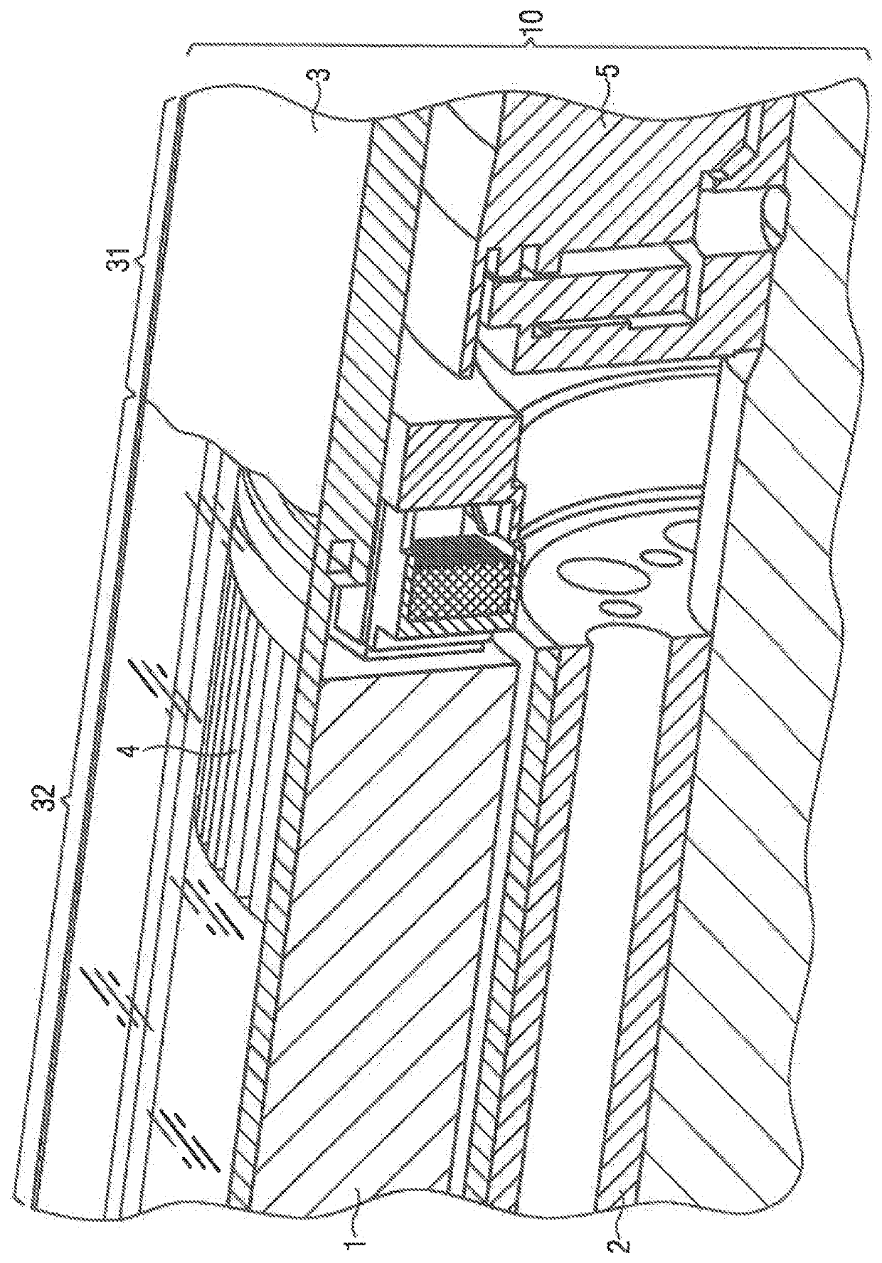
[0027]FIG. 1 shows a cross-section of an electric machine 10, which comprises a stator 1 and a rotor 2. In the right region 31 of the electric machine 10, a housing 3 can be seen, which is shown definitely available in the left region 32 of FIG. 1, but transparently. On account of a transparency of the housing 3, a deviation in shape which is realized as a knurling 4 in order to increase a coefficient of friction between the stator 1 and the housing 3 on the stator 1 can be identified.

[0028]The knurling 4 takes up a subarea of a contact area between the stator 1 and the housing 3 and is realized on a surface of the stator 1 which faces the housing 3. FIG. 1 shows that precisely one subarea is knurled. The knurling 4 is realized as a knurl with paraxial rills and allows for a force-fit and form-fit connection of the stator 1 to the housing 3.

[0029]The knurling 4 is embodied at one end, on a so-called B-side of the electric machine, of the stator 1, which borders a bearing shield 5. T...


PUM


Abstract

A stator-housing unit for an electric machine includes a housing and a stator connected to the housing and bordering a bearing shield. A deviation in shape for increasing a coefficient of friction between the stator and the housing is realized on at least one subarea of a contact area between the stator and the housing, with the subarea being realized at one end of the stator.

Description

CROSS-REFERENCES TO RELATED APPLICATIONS[0001]This application is the U.S. National Stage of International Application No. PCT / EP2018 / 065517, filed Jun. 12, 2018, which designated the United States and has been published as International Publication No. WO 2019 / 007646 A1 and which claims the priority of European Patent Application, Serial No. 17180018.8, filed Jul. 6, 2017, pursuant to 35 U.S.C. 119(a)-(d).BACKGROUND OF THE INVENTION[0002]The invention relates to a stator-housing unit for an electric machine, wherein a stator is connected to a housing.[0003]In order to fasten a stator of an electric machine in a housing provided therefor, it must be ensured that a torque deriving from a rotor of the electric machine can be transmitted from the stator to the housing. Rotation of the rotor in principle has an impact on the stator, as a result of which this has to be connected to the housing in a force-fit manner in order to prevent the stator from rotating jointly with the rotor.[0004...

Claims


Application Information

Patent Timeline
IPC IPC(8): H02K1/18H02K5/15
CPCH02K1/185H02K5/15H02K5/04
Inventor HAUN, DOMINIKKESSLER, WINFRIED
Owner SIEMENS AG
Why Eureka
Try Eureka