Multilayer ceramic capacitor

a multi-layer ceramic and capacitor technology, applied in the direction of fixed capacitor details, stacked capacitors, fixed capacitors, etc., can solve the problems of lowering the the likelihood of short-circuiting between internal electrode layers is more, and the reliability tends to be less, so as to achieve the effect of less likelihood and high reliability of high-temperature load

Active Publication Date: 2022-06-28
MURATA MFG CO LTD
View PDF14 Cites 0 Cited by
  • Summary
  • Abstract
  • Description
  • Claims
  • Application Information

AI Technical Summary

Benefits of technology

[0012]A primary object of the present invention is to provide a multilayer ceramic capacitor that solves the problem above, the multilayer ceramic capacitor being less likely to suffer from fracture or chipping and high in high-temperature load reliability.

Problems solved by technology

Under the influence of the height difference, the internal electrode layer tends to be bent, which leads to tendency of short-circuiting between the internal electrode layers or lowering in high-temperature load reliability.
In particular, as the dielectric ceramic layer is smaller in thickness and as the number of layered internal electrode layers and dielectric ceramic layers is larger, short-circuiting between internal electrode layers is more likely and reliability tends to lower.
In this case again, however, under the influence of a small gap between the internal electrode pattern and the ceramic green sheet for eliminating the height difference, a bent portion is formed in the internal electrode layer in the fired multilayer body, which may lead to occurrence of fracture or chipping of the multilayer body or lowering in high-temperature load reliability.

Method used


Image

  • Multilayer ceramic capacitor
  • Multilayer ceramic capacitor
  • Multilayer ceramic capacitor

Examples


Embodiment Construction

[0037]An embodiment of the present invention is shown below and features of the present invention will specifically be described.

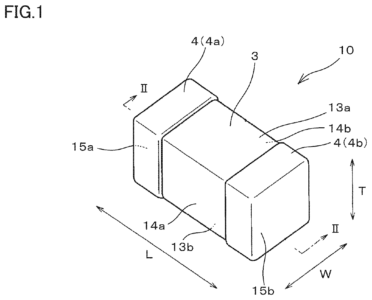
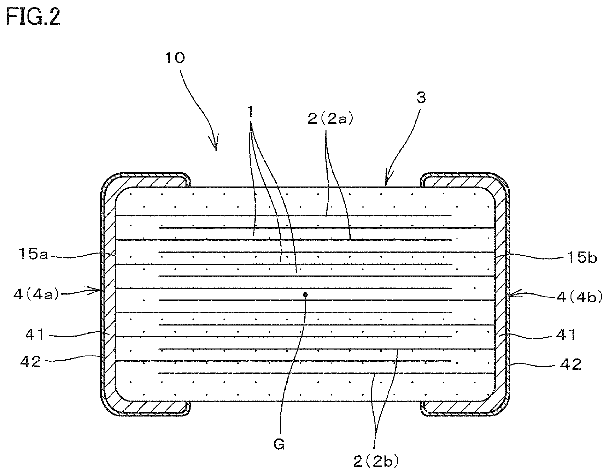
[0038]FIGS. 1 and 2 are a perspective view and a front cross-sectional view of a multilayer ceramic capacitor according to one embodiment of the present invention, respectively.

[0039]As shown in FIGS. 1 and 2, a multilayer ceramic capacitor 10 is generally in a shape of a parallelepiped and includes a multilayer body 3 including a plurality of dielectric ceramic layers 1 and a plurality of internal electrode layers 2 (2a and 2b) that are layered and an external electrode 4 (4a and 4b) disposed to conduct to internal electrode layers 2 at a prescribed position of multilayer body 3.

[0040]Multilayer body 3 includes a first main surface 13a and a second main surface 13b opposed to each other in a direction of layering T of dielectric ceramic layers 1 and internal electrode layers 2, a first side surface 14a and a second side surface 14b opposed to each other i...


PUM

PropertyMeasurementUnit
thicknessaaaaaaaaaa
thicknessaaaaaaaaaa
thicknessaaaaaaaaaa

Abstract

An Mn / Ti peak intensity ratio in a dielectric ceramic layer in an end surface outer layer portion is within two times to fifteen times of the Mn / Ti peak intensity ratio in a central portion, a rare earth element / Ti peak intensity ratio in the dielectric ceramic layer in the end surface outer layer portion is within two times to seven times the rare earth element / Ti peak intensity ratio in the central portion, an Si / Ti peak intensity ratio in the dielectric ceramic layer in a side surface outer layer portion is within two times to five times the Si / Ti peak intensity ratio in the central portion, and the rare earth element / Ti peak intensity ratio in the dielectric ceramic layer in the side surface outer layer portion is within two times to seven times the rare earth element / Ti peak intensity ratio.

Description

CROSS REFERENCE TO RELATED APPLICATIONS[0001]The present application claims priority to Japanese Patent Application No. 2020-045014, filed Mar. 16, 2020, the entire contents of which are incorporated herein by reference.BACKGROUND OF THE INVENTIONField of the Invention[0002]The present invention relates to a ceramic capacitor and specifically to a multilayer ceramic capacitor structured such that a plurality of dielectric ceramic layers and a plurality of internal electrode layers are layered.Description of the Background Art[0003]A multilayer ceramic capacitor structured such that an external electrode is disposed on opposing end surfaces of a multilayer body including layered dielectric ceramic layers and internal electrode layers to conduct to the internal electrode layers has conventionally widely been used.[0004]Japanese Patent Laid-Open No. 2006-73623 describes a multilayer ceramic capacitor structured as such, the multilayer ceramic capacitor including an element main body in...

Claims


Application Information

Patent Timeline
Patent Type & Authority Patents(United States)
IPC IPC(8): H01G4/30H01G4/12H01G4/008H01G4/012
CPCH01G4/1227H01G4/008H01G4/012H01G4/30H01G4/1209H01G4/0085H01G4/12H01G4/224
Inventor SASABAYASHI, TAKEHISASHIMADA, YASUYUKIMURANISHI, NAOTOKOKAWA, SHINICHI
Owner MURATA MFG CO LTD
Why Eureka
Try Eureka