Side-release buckle

a side-release buckle and buckle technology, which is applied in the direction of bracelets, wristwatch straps, buckles, etc., can solve the problems of low effect of preventing the other portion of the leg portion from being broken, forming cracks in the leg portion, and not being useful in preventing the other portion of the leg portion,

Active Publication Date: 2022-07-05
YKK CORP
View PDF21 Cites 3 Cited by
  • Summary
  • Abstract
  • Description
  • Claims
  • Application Information

AI Technical Summary

Benefits of technology

[0009]As described above, techniques that aim at preventing the leg portions from being damaged in a side-release buckle is known. However, the technique disclosed in Japanese Patent Publication No. 2010-022807 can prevent the breakage of the protrusion of the leg portion, that is, the engaging portion, but is not very useful for preventing the other portion of the leg portion, particularly the leg portion from being broken. Besides, the technique described in Japanese Patent Publication No. 2009-011492 has a high effect of preventing breakage of the leg portion when a tensile force is applied in a direction in which the leg portion is opened outwardly. However, the effect of preventing the leg portion from being broken is low when a tensile force is applied from belts on both sides in a direction in which the plug and the socket are separated from each other.
[0010]In a buckle, when the plug and the socket are locked by an insertion engagement, tensile force may be applied from the belts on both sides in the direction in which the plug and the socket are separated from each other due to various external factors. When such a tensile force is repeatedly applied or a strong tensile force is applied, a crack may be formed in the leg portion, and the leg portion may be finally broken. The conventional side-release buckle has not been sufficiently studied to prevent the leg portion from breaking in such a case, and there is still room for improvement. It is practically advantageous to be able to suppress the breakage of the leg portion from the viewpoint of increasing the reliability of the buckle. Therefore, an object of the present invention is to provide a side-release buckle in which the leg portions are hard to be broken when a tensile force is applied from the belts on both sides in a direction in which the plug and the socket are separated from each other.
[0015]Each of the engaging surface (129) and the surface to be engaged (149) needs to have a mountain-like shape with the end point of the parting line as a vertex in order to be able to take them out of a mold. The present inventor has found that there is a clearance between the engaging surface (129a) and the surface to be engaged (149a), and when the above-described tensile force is applied, the engaging surface (129a) on the opposite side to the belt winding portion of the plug with respect to the parting line is easily bent forward in the direction approaching the surface to be engaged (149a) (the direction of the arrow in FIG. 3-3).
[0036]Regarding the side-release buckle according to the present invention, forward bending of the plug is suppressed when a tensile force is applied from the belts on both sides in a direction in which the plug and the socket are separated from each other. Therefore, according to the present invention, when tensile force is applied from the belts on both sides in the direction in which the plug and the socket are separated from each other, the bending stress on the leg is reduced, and the leg is less likely to be broken. This is a practically advantageous effect and makes it possible to improve the reliability of the side-release buckle.

Problems solved by technology

However, the technique disclosed in Japanese Patent Publication No. 2010-022807 can prevent the breakage of the protrusion of the leg portion, that is, the engaging portion, but is not very useful for preventing the other portion of the leg portion, particularly the leg portion from being broken.
However, the effect of preventing the leg portion from being broken is low when a tensile force is applied from belts on both sides in a direction in which the plug and the socket are separated from each other.
When such a tensile force is repeatedly applied or a strong tensile force is applied, a crack may be formed in the leg portion, and the leg portion may be finally broken.
The conventional side-release buckle has not been sufficiently studied to prevent the leg portion from breaking in such a case, and there is still room for improvement.
Further, it has been found that when a force is applied in the direction of bending forward, bending stress is applied to the leg portions of the plug, which causes the leg portions to break.

Method used


Image

  • Side-release buckle
  • Side-release buckle
  • Side-release buckle

Examples


first embodiment

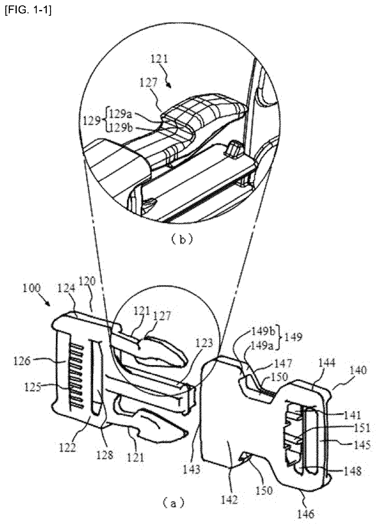
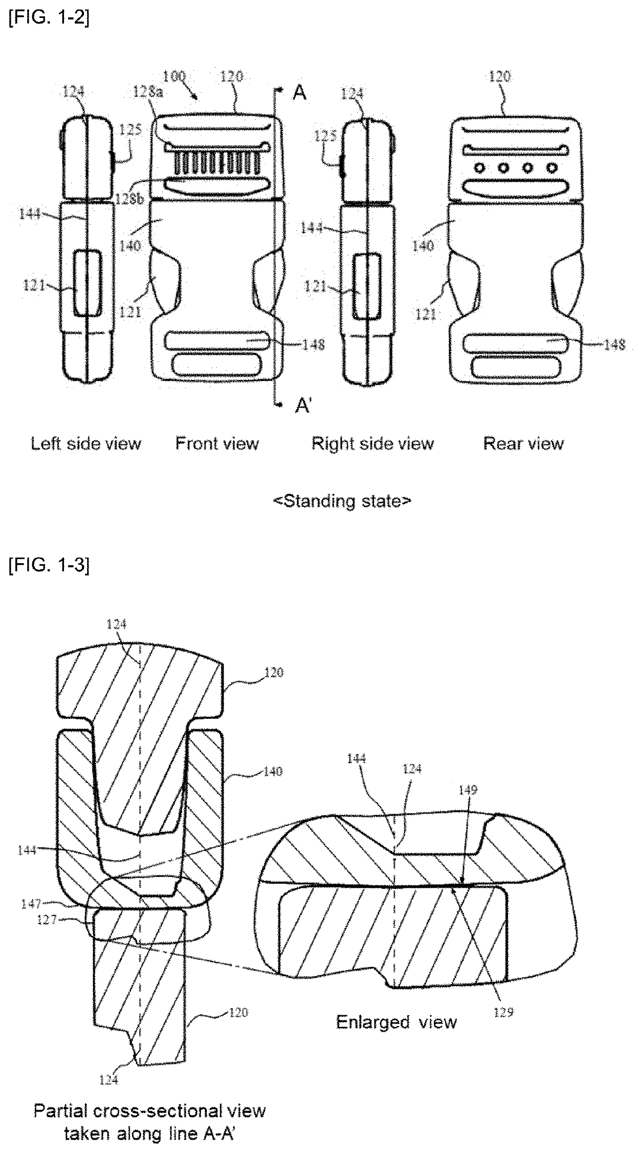
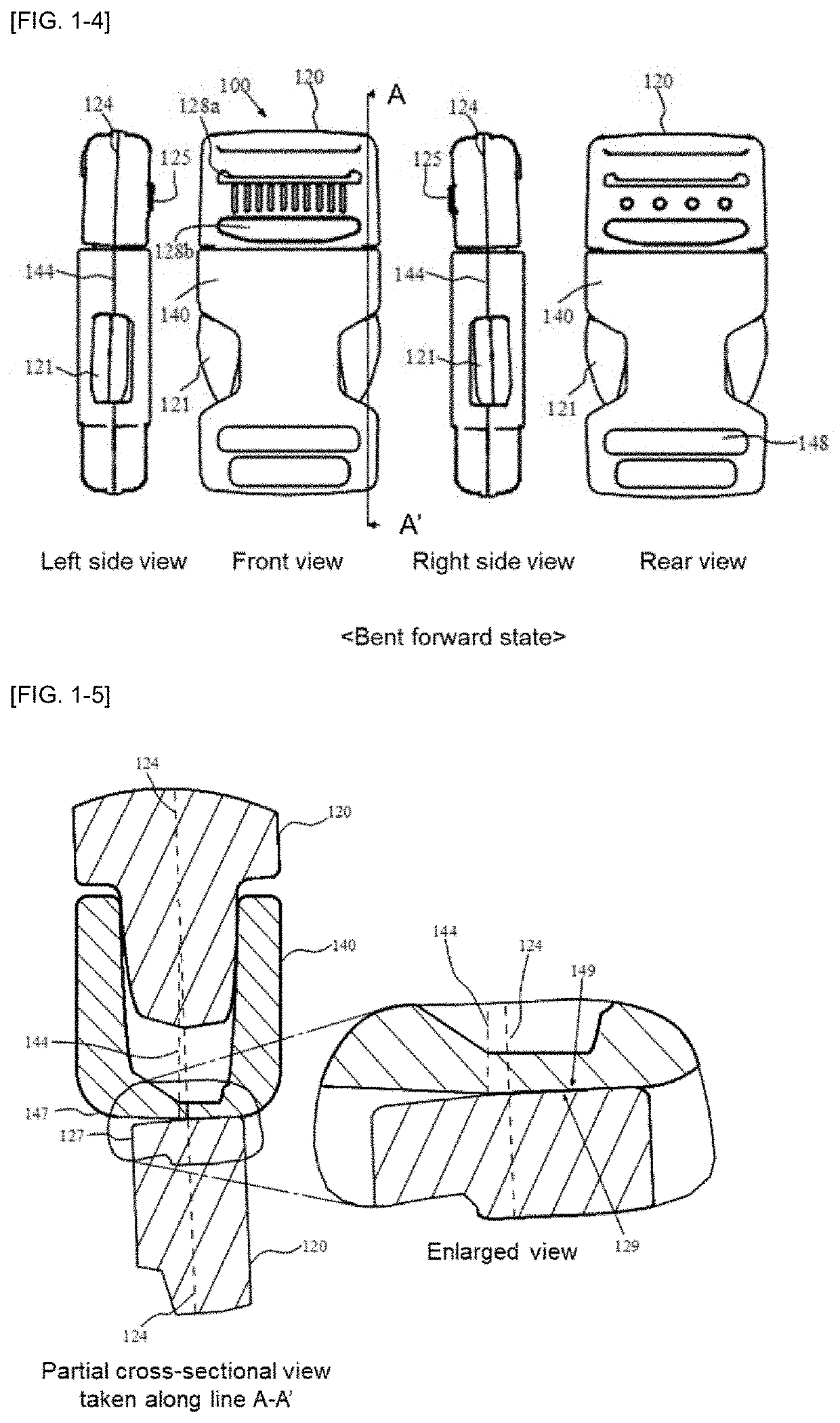
[0052]FIG. 1-1(a) is a perspective view of the side-release buckle (100) according to the first embodiment of the present invention when the plug (120) and the socket (140) are in a separated state. FIG. 1-1(b) is a partial enlarged view of the vicinity of the area surrounded by the circle in (a). FIG. 1-2 is a front view, a rear view, a right side view, and a left side view of the side-release buckle (100) wherein the plug (120) and the socket (140) are in a locked state and both parting lines are in a parallel state. FIG. 1-3 is an enlarged cross-sectional view of the vicinity of the engaging portion (127) of the plug (120) and the portion to be engaged (147) of the socket (140), taken along the line A-A′ of FIG. 1-2. FIG. 1-4 is a front view, a rear view, a right side view, and a left side view of the side-release buckle (100), wherein the plug (120) and the socket (140) are in a locked state and the plug (120) is in a bent forward state. FIG. 1-5 is an enlarged cross-sectional v...

second embodiment

[0071]FIG. 2-1 is a front view, a rear view, a right side view, and a left side view of the side-release buckle (200) according to a second embodiment of the present invention wherein the plug (120) and the socket (140) are in a locked state. FIG. 2-2 is an enlarged cross-sectional view of the vicinity of the engaging portion (127) of the plug (120) and the portion to be engaged (147) of the socket (140), taken along the line B-B′ of the side-release buckle (200) in FIG. 2-1. Further, FIG. 2-3 is a schematic cross-sectional view of the engaging surface (129) and the surface to be engaged (149) of the side-release buckle (200), in which the plug (120) and the socket (140) are locked, observed from a direction that is an in-plane direction of the first mold mating surface defined by the first parting line (124) of the plug (120), and is also a direction perpendicular to an insertion direction. In FIG. 2-1, FIG. 2-2, and FIG. 2-3, when the same reference numerals as FIG. 1-1, FIG. 1-2,...


PUM


Abstract

A side-release buckle includes a plug and a socket for inserting and engaging the plug, and when a cross section of the engaging surface is observed from an in-plane direction of the first mold mating surface defined by a first parting line of the plug, and from an direction perpendicular to an insertion direction, a surface to be engaged is located on the opposite side to a first belt winding portion with respect to the first mold mating surface, and has a first engaging surface forming an angle A1 with the first mold mating surface of 87° or more and 90° or less.

Description

CROSS-REFERENCE TO RELATED APPLICATIONS[0001]This application is a U.S. National Stage entry of PCT Application No: PCT / JP2017 / 033603 filed on Sep. 15, 2017, the contents of which are incorporated herein by reference.TECHNICAL FIELD[0002]The present invention relates to a side-release buckle used for connecting belts and having a pair of leg portions (lock arms) on both sides.BACKGROUND ART[0003]Conventionally, in addition to belts, in order to connect ends of belts attached to various articles such as bags, rucksacks, clothes, shoes, helmets, sporting goods, and wrappers, buckles for detachably engaging a plug and a socket are used. In such buckles, it is required that the operation for attaching and detaching be easy, and at the same time that buckles should not come off accidentally when not intended. As a product meeting such a demand, a side-release buckle having a pair of leg portions on both sides is known.[0004]Generally, a side-release buckle includes a plug and a socket ea...

Claims


Application Information

Patent Timeline
Patent Type & Authority Patents(United States)
IPC IPC(8): A44B11/25A44C5/20
CPCA44B11/25A44C5/2066A44B11/266
Inventor YOSHIE, KENICHI
Owner YKK CORP
Why Eureka
Try Eureka