
Method for electromagnetic interference (EMI) protection for a high voltage connector assembly having a high voltage vertical disk ferrule

a technology of electromagnetic interference and high voltage connectors, which is applied in the direction of coupling bases/cases, coupling device connections, electrical devices, etc., can solve the problems of affecting the effectiveness of data paths, affecting the performance of circuits, and preventing them from functioning,

Active Publication Date: 2022-07-05
J S T CORP
View PDF6 Cites 0 Cited by
  • Summary
  • Abstract
  • Description
  • Claims
  • Application Information

AI Technical Summary

Benefits of technology

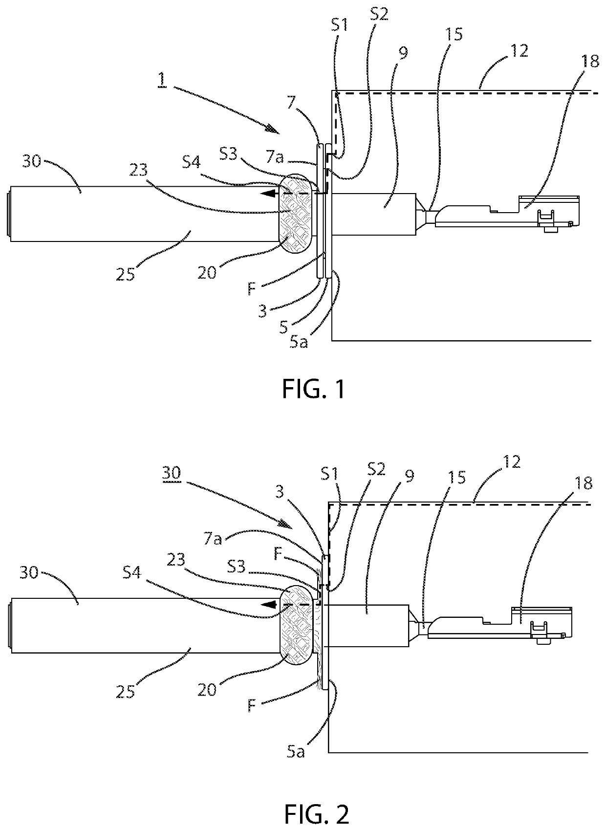
[0006]The vertical disk ferrule of the high voltage connector assembly slides over the core insulation, once affixed to the wire braided shield, towards the point or location where the outer insulation is cut (vertical surface of the outer insulation). The wire braided shield is pushed back and allows for the wire braided shield to develop a natural spring force against the vertical disk ferrule, and the wire braided shield becomes in the condition or state where it has compressed, accordioned, pleated, or folded against itself, and therefore pushes back against the direction the ferrule has traveled along the wire core when the wire is being pushed, so as to push the vertical disk ferrule forward (towards the cut end of the wire or terminal that is attached thereto). This force allows the high voltage vertical disk ferrule or wire braided shield of the high voltage connector assembly, if therebetween, to remain in contact with the grounding structure of the high voltage connector assembly when in use or when as a single high voltage vertical disk ferrule, pushes the wire braided shield against the housing or ferrule when in use.
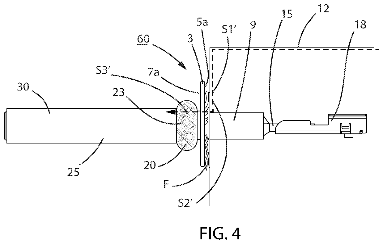
[0007]The ability of the structural arrangements, in different embodiments, of the high voltage disk-like structure of the high voltage vertical disk ferrule of the high voltage connector assembly to take on any shape to which it can be stamped allows for it to provide complete or near complete electromagnetic interference (EMI) coverage in use with a corresponding metallic connector housing which may require a specific shape, and which further allows for little or no escape path for the EMI by covering the aperture or hole through which the wire or terminal is placed into when in use with such corresponding metallic connector housing in which the wire or terminal is inserted into, unlike in conventional ferrules and conventional stamped shields which may allow for EMI escape.
[0008]The high voltage vertical disk ferrule of the high voltage connector assembly in this invention also provides for an adequate clearance between the wire core or terminal (power circuit), and the wire braid shield or ferrule (grounding circuit), while also limiting the likelihood of contact between the power circuit and grounding circuit in the process by also limiting the likelihood of stray strands of the wire braid shield from contacting the power circuit.

Problems solved by technology

EMI may degrade the performance of a circuit or may even stop it from functioning.
In the case where the circuit includes a data path, EMI may affect the effectiveness of the data path due to an increase in error rate to the total loss of the data.

Method used


Image

  • Method for electromagnetic interference (EMI) protection for a high voltage connector assembly having a high voltage vertical disk ferrule
  • Method for electromagnetic interference (EMI) protection for a high voltage connector assembly having a high voltage vertical disk ferrule
  • Method for electromagnetic interference (EMI) protection for a high voltage connector assembly having a high voltage vertical disk ferrule

Examples


first embodiment

[0025]Shown in FIG. 1 is the high voltage connector assembly 1 and is the preferable use of two vertical disk ferrules 5, 7. The use of two vertical disk ferrules 5, 7, the first vertical disk ferrule 5 and the second vertical disk ferrule 7, provides the ability to sandwich a flared portion of the wire braided shield 23 of the wire 30 in between the front face 5a of the first vertical disk ferrule 5 and the rear face 7a of the second vertical disk ferrule 7. The first vertical disk ferrule 5 has been placed over the wire braided shield portion 23, such that the first vertical disk ferrule 5 and the second vertical disk ferrule 7 contact the flared portion F of the wire braided shield 23. The above-described structural arrangement provides adequate contact among the flared portion F of the wire braided shield 23, the first vertical disk ferrule 5, and the second vertical disk ferrule 7. Solder or other mechanical, or electro-mechanical means, (not shown) may be used to further stabi...

third embodiment

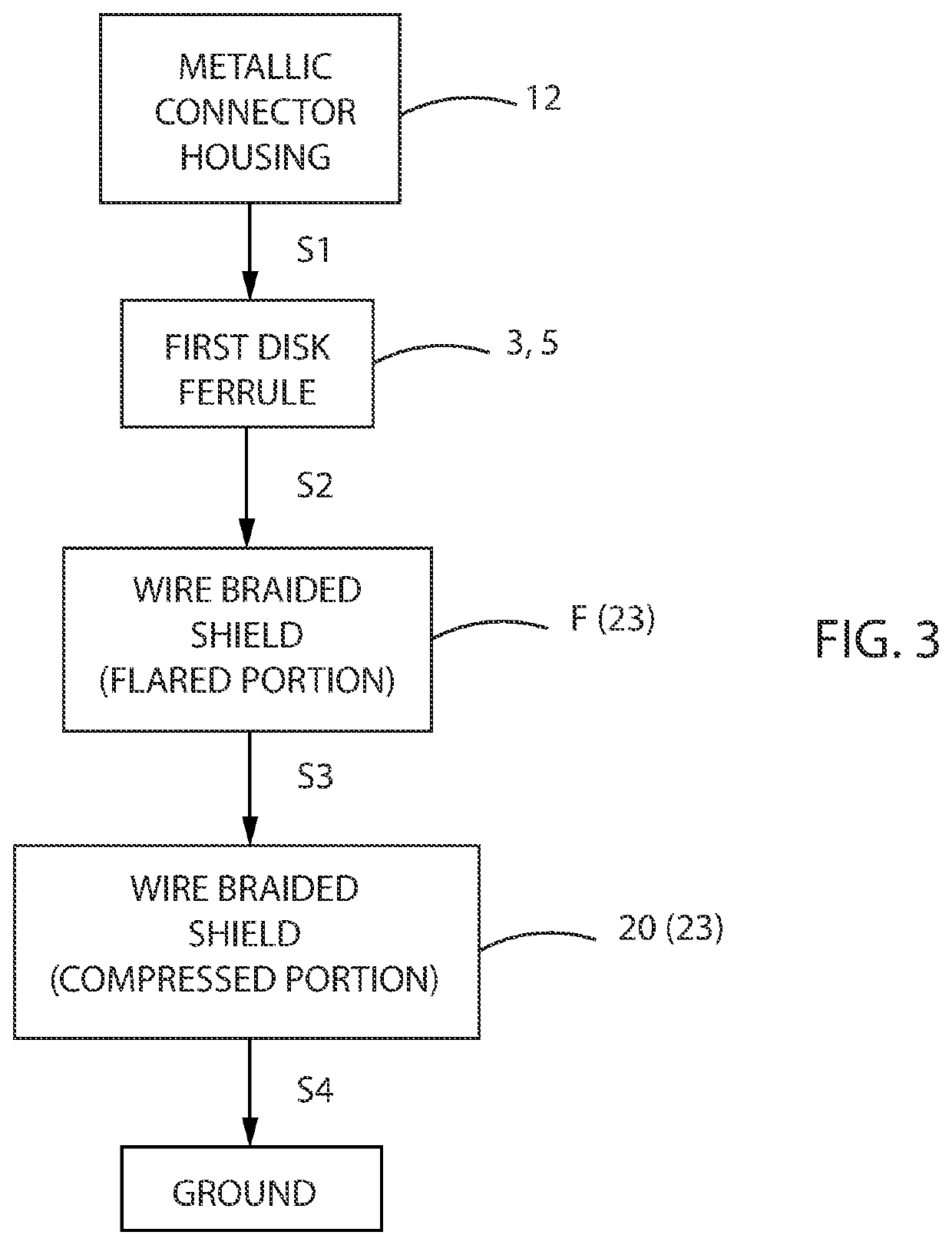
[0035]FIG. 5 is a flowchart illustrating the path taken by the EMI along the high voltage connector assembly 60, which employs the high voltage vertical disk ferrule 3. As shown in FIG. 5, the EMI, in Step 1′ (S1′), travels from the metallic connector housing 12 directly to the flared portion of the wire braided shield 23, the flared portion F abutting and contacting the metallic connector housing 12. The EMI, in Step 2′ (S2′), then travels from the flared portion F directly to the compressed portion 20 of the wire braided shield 23, the flared portion F of the wire braided shield 23 being connected to the compressed portion 20 of the wire braided shield 23. In Step 3′ (S3′), the EMI travels directly from the compressed portion 20 of the wire braided shield 23 to ground.

[0036]The high voltage vertical disk ferrule 3 (5, 7) employed in the high voltage connector 1, 30, 60 of this invention also increases the electrical clearance when in operation. In other words, by allowing the vert...


PUM


Abstract

A method for reducing the effect of electromagnetic interference (EMI), providing EMI protection to a connector assembly, using at least one vertical disk ferrule. The method includes steps of providing a flared portion, first portion, of a wire shield to at least a vertical disk ferrule, or affixing between two of said vertical disk ferrules. Further, one of a step of providing a ferrule having a face which contacts a metallic connector housing directly; or providing the flared portion of the wire shield which contacts said metallic connector housing directly; wherein said EMI is conducted from said metallic connector housing to said ferrule or flared portion, further conducting said EMI to said flared portion of the wire shield, further conducting said EMI through a second portion of said wire shield, further conducting said EMI to ground; said EMI being generated by at least the metallic connector housing.

Description

CROSS-REFERENCE TO RELATED APPLICATION[0001]This patent application claims priority to U.S. Provisional Patent Application No. 63 / 051,517 filed. Jul. 14, 2020, which is hereby incorporated herein by reference in its entirety.BACKGROUND OF THE INVENTION[0002]Electromagnetic interference (EMI) affects an electrical circuit due to a disturbance, from a source, by electromagnetic induction, electrostatic coupling or conduction. EMI may degrade the performance of a circuit or may even stop it from functioning. In the case where the circuit includes a data path, EMI may affect the effectiveness of the data path due to an increase in error rate to the total loss of the data. A source that may generate changing electrical currents and voltage that may cause EMI may include, for example, automotive injection systems, mobile phone cellular network, or the like. It is thus essential to manage the generation of EMI to avoid the detrimental effects caused by it; and to consequently maximize the ...

Claims


Application Information

Patent Timeline
Patent Type & Authority Patents(United States)
IPC IPC(8): H01R13/53H01R13/6591H01R13/405H01R13/6583
CPCH01R13/53H01R13/405H01R13/6583H01R13/65912H01R13/65914H01R2201/26H01R9/0524H01R13/6592H01R9/0512
Inventor DEMARATOS, DAVIDTAYLOR, JOSHUA
Owner J S T CORP
Learn More