
Apparatus and method for performing beamforming using multiple antennas in wireless AV system

a wireless av system and antenna technology, applied in the direction of multi-antenna systems, spatial transmit diversity, digital transmission, etc., can solve the problems of increasing transmission costs, mimo beamforming may not meet the requirements of low latency and high reliability of wireless av systems

Active Publication Date: 2022-07-05
LG ELECTRONICS INC
View PDF8 Cites 0 Cited by
  • Summary
  • Abstract
  • Description
  • Claims
  • Application Information

AI Technical Summary

Benefits of technology

This patent aims to speed up the process of MIMO beamforming in wireless communication by using an optimum sector combination. This reduces the time required for training and minimizes the impact on information related to MIMO beamforming. The technical effect is a more efficient and reliable wireless AV system.

Problems solved by technology

Therefore, transmission cost may increase when the picture data is transmitted using a medium such as the existing wired / wireless broadband line.
However, when the MIMO beamforming is performed according to a sweep for all possible combinations per antenna and sector, it may take a considerable amount of time for the MIMO beamforming.
In a specific environment where peer devices are potentially fixed similarly to the wireless AV system, the MIMO beamforming scheme may not meet a requirement of the wireless AV system pursuing low latency and high reliability, and may operate without problems even if some procedures are omitted, reduced, or changed.

Method used


Image

  • Apparatus and method for performing beamforming using multiple antennas in wireless AV system
  • Apparatus and method for performing beamforming using multiple antennas in wireless AV system
  • Apparatus and method for performing beamforming using multiple antennas in wireless AV system

Examples


Embodiment Construction

[0041]Hereinafter, embodiments of a wireless data transmitting device and method and a wireless data receiving device and method are described in detail according to the present disclosure, but the present disclosure is not limited thereto. Features of the present disclosure are described by the illustrated embodiments. However, functions and structures identical or equivalent to the embodiments described in the present specification are included within the spirit and scope of the present disclosure, and may also be achieved by other intended embodiments. Throughout the present specification, like reference numbers indicate like parts or features. Hereinafter, embodiments of the present disclosure will be described in detail with reference to the accompanying drawings.

[0042]Recently, a design of a display device such as a TV is becoming more important, and a display panel is gradually becoming thinner with the development of a display panel technology such as OLED. However, there is...


PUM


Abstract

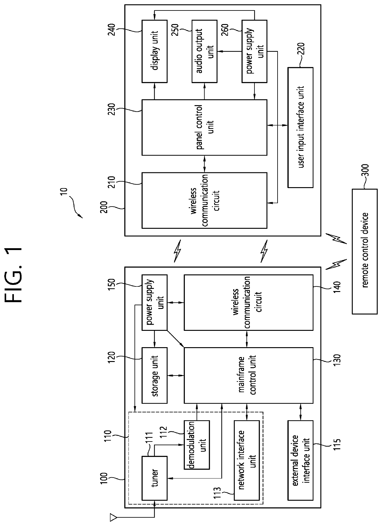
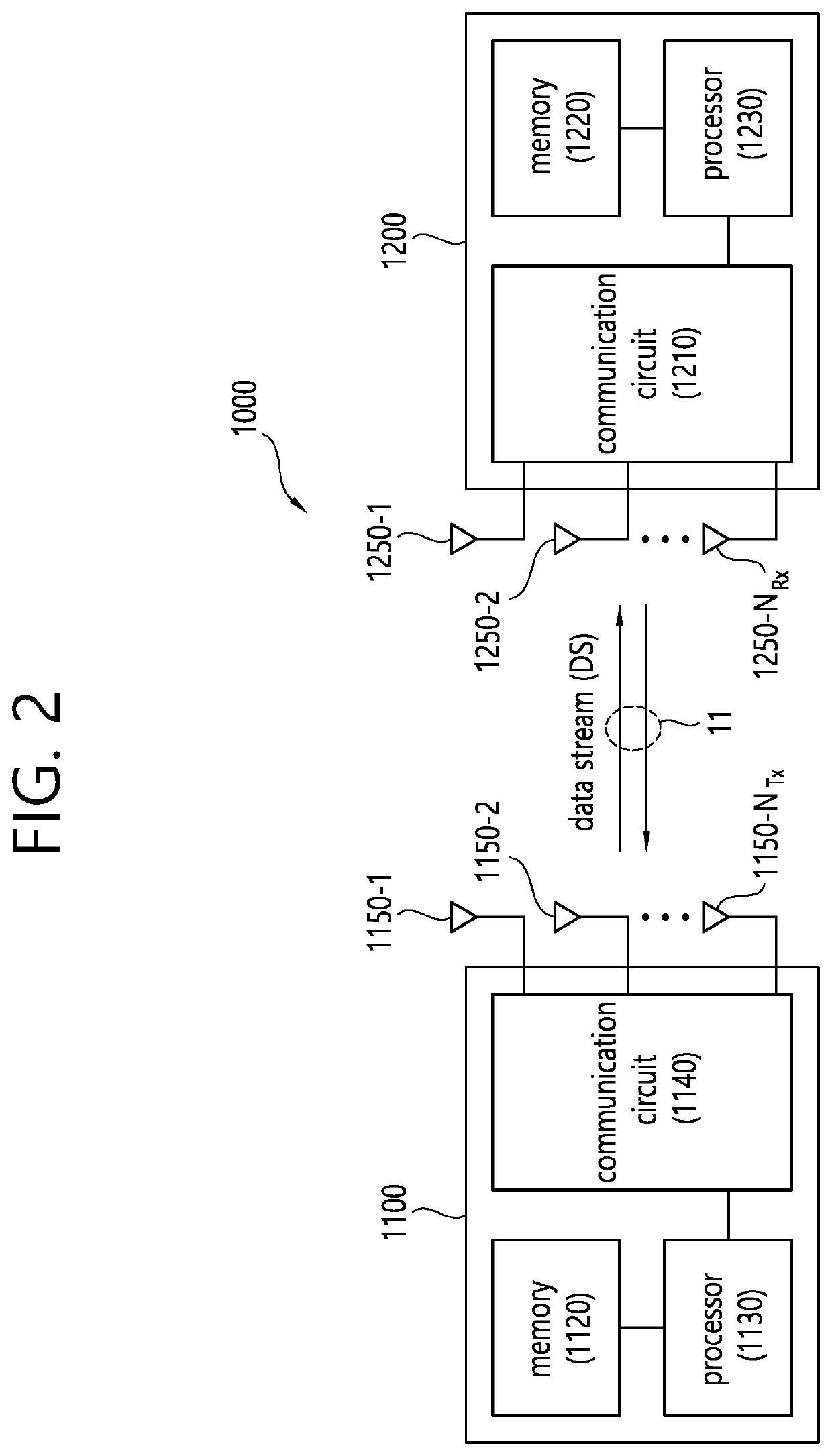
The present invention relates to an apparatus and a method for performing beamforming using multiple antennas in a wireless AV system. The present specification discloses a wireless data transmission apparatus comprising: a plurality of transmission antennas; a communication circuit for performing a MIMO beamforming procedure on the basis of an individual transmission sector sweep for each of the plurality of transmission antennas during a data transmission interval within a beacon interval, and transmitting a physical layer protocol data unit (PPDU) frame to a wireless data reception apparatus through the plurality of transmission antennas; and a processor connected to the communication circuit, and configured to generate AV data to be transmitted through the PPDU frame and provide the generated AV data to the communication circuit. The present invention can reduce time required for MIMO beamforming while minimizing training of an excessive sector combination in a communication procedure or information related to the MIMO beamforming in a wireless AV system, and maintain the reliability of the system by using an optimum sector combination.

Description

CROSS-REFERENCE TO RELATED APPLICATIONS[0001]This application is the National Stage filing under 35 U.S.C. 371 of International Application No. PCT / KR2019 / 011736, filed on Sep. 10, 2019, which claims the benefit of U.S. Provisional Application No. 62 / 775,907, filed on Dec. 6, 2018, the contents of which are all incorporated by reference herein in their entirety.BACKGROUNDField of the Disclosure[0002]The present disclosure relates to a wireless audio / video (AV) system, and more particularly, to an apparatus and method for performing beamforming using multiple antennas in the wireless AV system.Related Art[0003]Recently, there is a growing demand for high-resolution and high-quality pictures such as a high definition (HD) picture and an ultra-high definition (UHD) picture in various fields. The higher the resolution and quality of picture data, the greater the amount of information of bits to be transmitted relative to the existing picture data. Therefore, transmission cost may increa...

Claims


Application Information

Patent Timeline
Patent Type & Authority Patents(United States)
IPC IPC(8): H04B7/0413H04B7/06
CPCH04B7/0413H04B7/0617H04B7/0695H04L5/0023H04B7/0491H04B7/0408H04B7/088
Inventor KIM, JINMINBAE, HYOWONSONG, JAEWOOKLEE, KYUINCHOI, JINSOO
Owner LG ELECTRONICS INC
Learn More