
Microchip electrophoresis apparatus and microchip electrophoresis method

a microchip electrophoresis and microchip technology, applied in the direction of scientific instruments, measurement devices, instruments, etc., can solve the problems of affecting the liquid surface level of each of the reservoirs, the buffer solution in the reservoir remains unsucked, and the liquid surface level error in the reservoir

Active Publication Date: 2022-07-19
SHIMADZU CORP
View PDF12 Cites 0 Cited by
  • Summary
  • Abstract
  • Description
  • Claims
  • Application Information

AI Technical Summary

Benefits of technology

[0006]Accordingly, an object of the present invention is to improve the accuracy of controlling the liquid surface level in each of the reservoirs after the channel in the microchip is filled with the buffer solution.
[0018]In the microchip electrophoresis apparatus and the microchip electrophoresis method according to the present invention, when the buffer solution is filled in the channel of the microchip, the liquid surface levels of the buffer solution in the first reservoir and the second reservoir reach to the predetermined level or more, and thereafter, the buffer solution in the first reservoir and the second reservoir is sucked in order from the surface layer side by the first suction nozzle and the second suction nozzle to align the respective liquid levels with each other in the predetermined liquid level. Accordingly, the accuracy of the liquid surface level of the buffer solution in each of the reservoirs depends only on the lowering accuracy of the tips of the first suction nozzle and the second suction nozzle, and the accuracy of controlling the liquid surface level in each of the reservoirs is improved.

Problems solved by technology

However, when the buffer solution in each of the reservoirs is sucked after the buffer solution is filled in the channel, there is a concern that the buffer solution in the reservoir remains unsucked.
The unsucked buffer solution in the reservoir causes an error in the liquid surface level in the reservoir.
Furthermore, accuracy of a dispensing amount of the buffer solution into the reservoir after the buffer solution is sucked from each of the reservoirs also affects the liquid surface level of each of the reservoirs.

Method used


Image

  • Microchip electrophoresis apparatus and microchip electrophoresis method
  • Microchip electrophoresis apparatus and microchip electrophoresis method
  • Microchip electrophoresis apparatus and microchip electrophoresis method

Examples


Embodiment Construction

[0031]Hereinafter, an embodiment of a microchip electrophoresis apparatus and a microchip electrophoresis method is described with reference to the drawings.

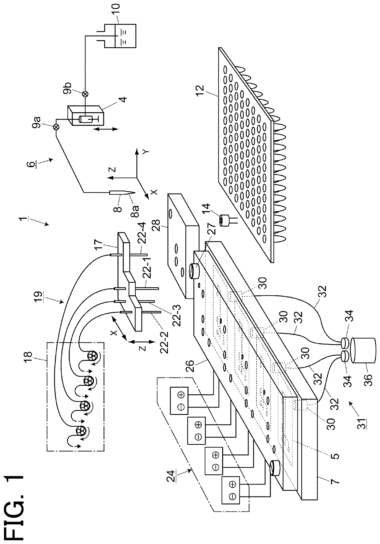
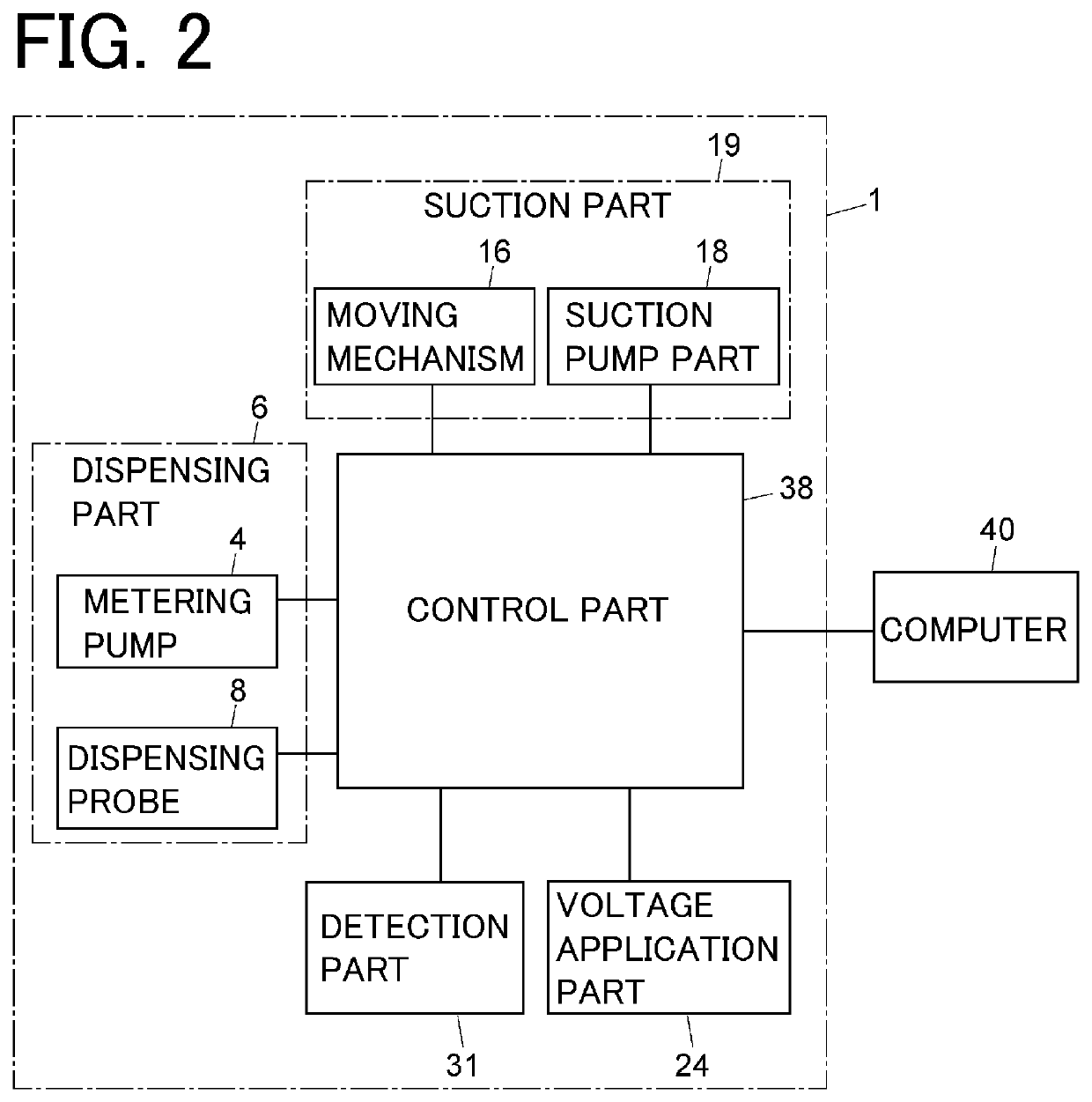
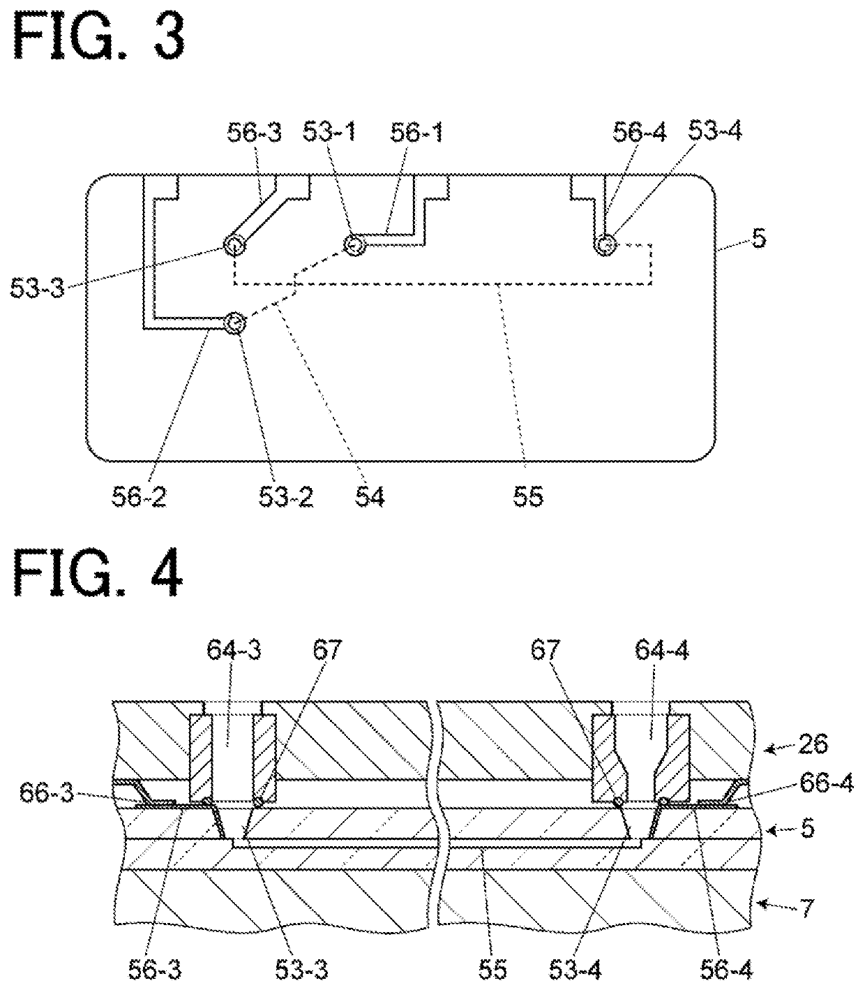
[0032]As shown in FIGS. 1 and 2, a microchip electrophoresis apparatus 1 mainly includes microchips 5, a dispensing part 6, a chip holding part 7, a suction part 19, a voltage application part 24, a detection part 31, and a control part 38. The microchips 5 are arranged on the chip holding part 7. In this embodiment, four microchips 5 are arranged on the chip holding part 7, but the number of microchips 5 is not limited. In FIG. 1, an expansion reservoir block 26 is arranged on the microchips 5, but the expansion reservoir block 26 is not an essential component.

[0033]In addition to a metering pump 4 and a dispensing probe 8, the dispensing part 6 includes a moving mechanism (not shown) that moves the dispensing probe 8 three-dimensionally in the horizontal direction (XY direction) and the vertical direction (Z direction). The di...


PUM

PropertyMeasurementUnit
liquid surface levelsaaaaaaaaaa
surface levelaaaaaaaaaa
viscosityaaaaaaaaaa

Abstract

A microchip electrophoresis apparatus includes a microchip, a dispensing part, a suction part, and a control part. The control part is configured to perform a buffer solution filling step and a liquid surface aligning step. In the buffer solution filling step, a buffer solution is filled in a channel of the microchip, and also a liquid surface level of the buffer solution in a first reservoir and a liquid surface level of the buffer solution in a second reservoir provided on the other end of the channel are set to a predetermined level or more. The liquid surface aligning step is performed after the buffer solution filling step. In the liquid surface aligning step, tips of a first suction nozzle and a second suction nozzle are lowered from above the first reservoir and the second reservoir to the predetermined level while allowing the first suction nozzle and the second suction nozzle to perform suction operation, such that the buffer solution in the first reservoir and the second reservoir is sucked in order from a surface layer side, and aligning the liquid surface level of the first reservoir with the liquid surface level of the second reservoir.

Description

BACKGROUND OF THE INVENTION1. Field of the Invention[0001]The present invention relates to a microchip electrophoresis apparatus and a microchip electrophoresis method.2. Description of the Related Art[0002]Microchip electrophoresis has a feature that separation detection can be performed at high speed by downsizing lengths of a separation channel and a sample plug which are provided in a microchip to minimum necessary lengths, and by performing electrophoresis using a relatively low viscosity solution.[0003]Reservoirs whose upper parts are open are provided at a position corresponding to a channel end part of the microchip. At the time of electrophoresis analysis, the separation channel is filled with a buffer solution for electrophoresis, and a predetermined amount of buffer solution is dispensed into the reservoirs at the channel end part. However, because flow resistance is small due to the short channel length and the buffer solution has low viscosity, if a level of the buffer ...

Claims


Application Information

Patent Timeline
Patent Type & Authority Patents(United States)
IPC IPC(8): G01N27/447
CPCG01N27/44791G01N27/44743G01N27/44773G01N27/4473G01N27/44704
Inventor ARAI, AKIHIRO
Owner SHIMADZU CORP
Learn More