Compact multi-sensor fusion system with shared aperture

a multi-sensor fusion and aperture technology, applied in scene recognition, instruments, computing, etc., can solve the problems of large data transmission to the computer for fusion, large quantities of data must be transmitted for fusion, and the image registration process is mathematically and computationally intensiv

Active Publication Date: 2022-07-19
CHARLES STARK DRAPER LABORATORY
View PDF11 Cites 0 Cited by
  • Summary
  • Abstract
  • Description
  • Claims
  • Application Information

AI Technical Summary

Benefits of technology

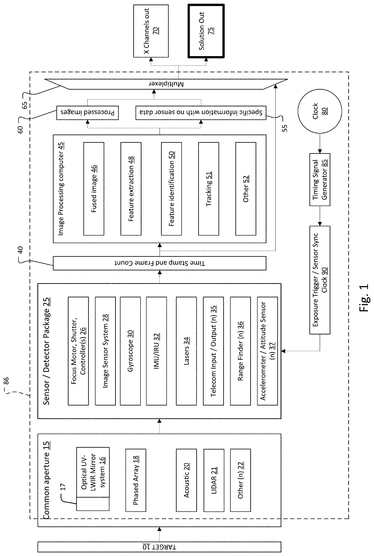
[0007]The present system can be used to simplify image registration and facilitate other data fusion by having multiple sensors packaged as a single unit, possibly mounted on a common gimbal, with a shared boresight and aperture. Moreover, the present system can utilize simultaneous or near-simultaneous measurement of data from a variety of active and passive sensors, such as image sensors, acoustic sensor, radio frequency sensors, range finders, accelerometers, etc.
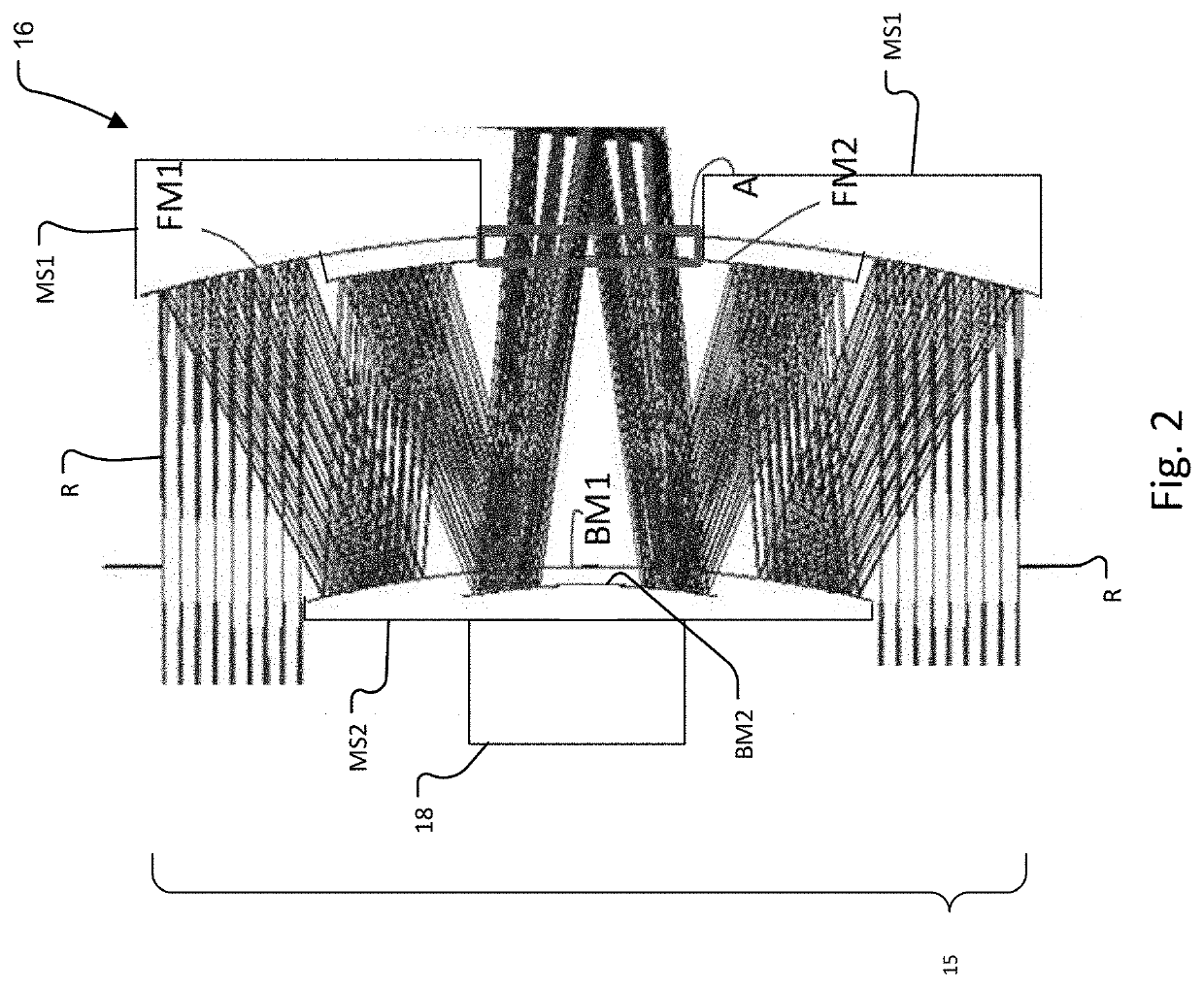
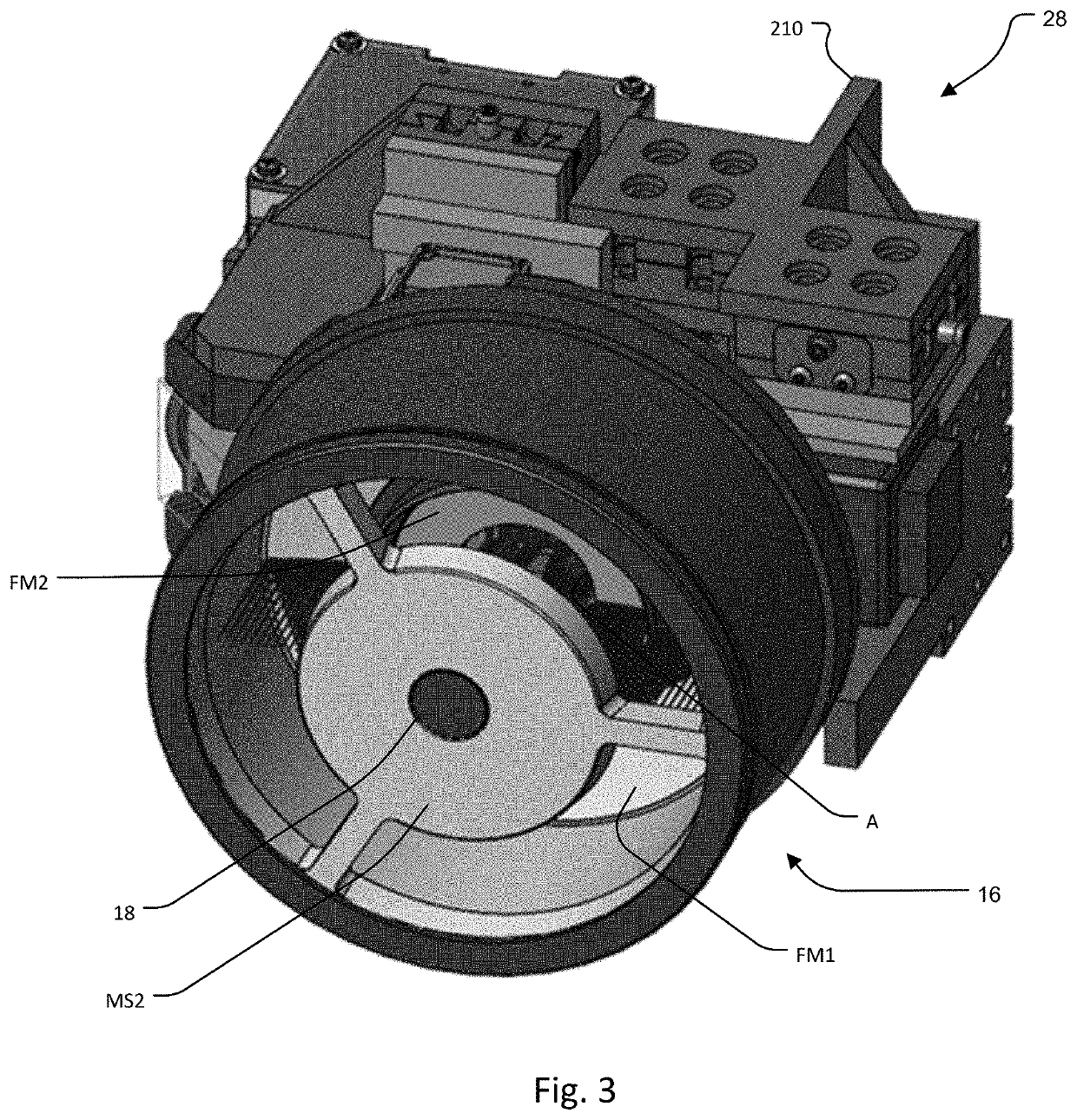
[0010]In contrast, in the present system, a single mirror system preferably collects the light for an image sensor system of the sensor package. A beamsplitter system might divide the collected light into separate spectral bands including the ultraviolet (UV), visible (VIS), and / or infrared (IR) bands, possibly including the short wave IR, medium wave IR (MWIR), and / or long wave IR (LWIR) bands. The use of the single mirror system helps to athermalize and make the system robust against vibration. Any mechanical distortion of the mirror system or in the mechanical coupling between the mirror system and the sensor package does not complicate image fusion since the effect of the vibration and distortion is the same for all of the image sensors.

Problems solved by technology

Typically, image registration process is mathematically and computationally intensive as it must reconcile platform motion, altitude, angle and field of view (FOV), pixel size (instantaneous field of view or IFOV, which is the field of view of one individual pixel on a detector), and possibly, account for atmospheric degradation of data, from one image sensor / spectral band to another.
In the past, a major challenge of fusing multi-sensor data is that processing of such data is typically performed at remote computers, due to the computationally intensive nature of the processing.
Thus, large quantities of data must be transmitted to the computers for fusion.

Method used


Image

  • Compact multi-sensor fusion system with shared aperture
  • Compact multi-sensor fusion system with shared aperture
  • Compact multi-sensor fusion system with shared aperture

Examples


Embodiment Construction

[0028]The invention now will be described more fully hereinafter with reference to the accompanying drawings, in which illustrative embodiments of the invention are shown. This invention may, however, be embodied in many different forms and should not be construed as limited to the embodiments set forth herein; rather, these embodiments are provided so that this disclosure will be thorough and complete, and will fully convey the scope of the invention to those skilled in the art.

[0029]As used herein, the term “and / or” includes any and all combinations of one or more of the associated listed items. Further, the singular forms and the articles “a”, “an” and “the” are intended to include the plural forms as well, unless expressly stated otherwise. It will be further understood that the terms: includes, comprises, including and / or comprising, when used in this specification, specify the presence of stated features, integers, steps, operations, elements, and / or components, but do not pre...


PUM


Abstract

A potentially small, gimballed, multi-sensor system employs a shared aperture for at least some of the image sensors. Applications include intelligence, surveillance, target acquisition and reconnaissance (ISTAR), and guiding autonomous vehicles. The system can actively blend images from multiple spectral bands for clarity and interpretability, provide remote identification of objects and material, provide anomaly detection, control lasers and opto-mechanics for image quality, and use shared aperture using folded optics.

Description

RELATED APPLICATIONS[0001]This application claims the benefit under 35 USC 119(e) of U.S. Provisional Application No. 62 / 690,639, filed on Jun. 27, 2018, which is incorporated herein by reference in its entirety.BACKGROUND OF THE INVENTION[0002]For autonomous machines, image data from multiple spectral bands must be processed simultaneously and in real-time for maximum situational awareness of surroundings. Unmanned aerial vehicles (UAVs) and self-driving automobiles, for example, must operate in a wide range of weather conditions, and both day and night, for missions including intelligence, surveillance, target acquisition and reconnaissance (ISTAR) and delivery and other governmental and commercial uses. For example, during the day, light in the visible spectral band is very useful. At night, however, visible will require active illumination. Thus, the ability to view the scene in the infrared might be preferred. Utilizing multiple spectral bands such as visible and infrared simul...

Claims


Application Information

Patent Timeline
Patent Type & Authority Patents(United States)
IPC IPC(8): G06K9/62G01S17/88G01S13/86
CPCG06K9/6289G01S13/867G01S17/88G01S17/86G01S15/86G01S13/862G01S13/865G01S2013/9327G01S7/4813G01S17/931G01S17/933G01S13/933G01S17/89G01S17/66G01S15/931G01S13/931G01S13/86G06V20/58G06V10/803G06F18/251
Inventor SINCLAIR, MATTHEW A.KELSEY, ADAMBOHN, PAUL AARONGOLMON, STEPHANIE L.ROGOMENTICH, FRANCIS J.LAINE, JUHA-PEKKACLEMMER, BUDDY A.LANDIS, DAVID A.
Owner CHARLES STARK DRAPER LABORATORY
Why Eureka
Try Eureka