
Antenna for receiving data from low earth orbit satellites

an antenna and satellite technology, applied in the direction of antennas, electrical equipment, etc., can solve the problems of complex mechanism for displacing the entire antenna structure, increasing the weight of the antenna structure, and difficult assembly and installation of the fram

Active Publication Date: 2022-07-26
GERSHENZON VLADIMIR EVGENIEVICH
View PDF11 Cites 0 Cited by
  • Summary
  • Abstract
  • Description
  • Claims
  • Application Information

AI Technical Summary

Benefits of technology

The present invention is a simple and easily mounted structure that allows for high-quality data reception from space using a long-focus antenna. This invention expands the variety of antenna systems available for use. The proposed positioner structure provides stable and steady feed movement, allowing for the reception of high-speed, high-resolution data streams from low-Earth-orbit satellite. Additionally, the offered antenna meets all structural security and durability requirements. Overall, this invention offers a technologically advanced and easy-to-install solution for receiving valuable data from space.

Problems solved by technology

However, this solution requires a complex mechanism for displacing the entire antenna structure.
The disadvantage of the prior art structure is that the antenna comprises two reflectors and several feeds, thus significantly increasing weight of the antenna structure.
The antenna frame which provides a support structure for two reflectors and means for moving feeds further contributes to weight of the structure; furthermore, the frame is complex and difficult to assemble and install.
However, the prior art antenna does not comprise automatic position re-tuning for the feed or antenna reflector; thus, the system requires an on-site visit by a specialist in order to redirect antenna to a different position.
Furthermore, the feed movability does not provide full use of the entire available antenna reflector aperture.
The disadvantage of the prior art antenna is that positioner axes are arranged in several planes with respect to the reflector plane; therefore, controlling the positioner becomes more difficult when moving the feed, thus increasing the risk of scanning error.
When using several antenna reflectors, the structure weight increases and the process of installing the antenna system becomes more complex.
However, prior art feed-motion antenna structures lack a feed positioner required for interaction with a long-focus reflector and providing high quality data reception from space.

Method used


Image

  • Antenna for receiving data from low earth orbit satellites
  • Antenna for receiving data from low earth orbit satellites
  • Antenna for receiving data from low earth orbit satellites

Examples


Embodiment Construction

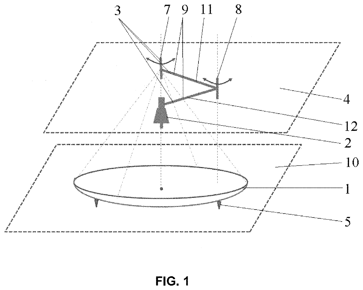
[0039]The proposed antenna for receiving data from low Earth orbit satellites comprises a long-focus antenna reflector with a moveable feed.

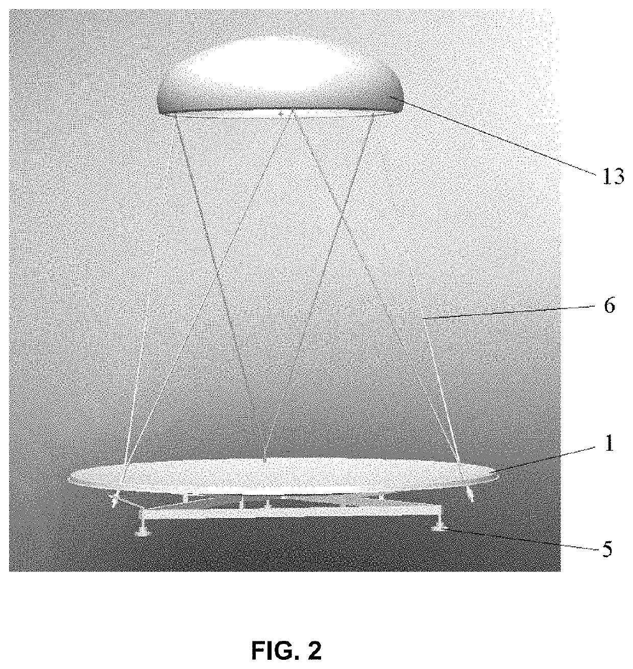
[0040]The antenna for receiving data from low Earth orbit satellites (FIG. 1) comprises a fixedly mounted antenna reflector 1 having a paraboloid shape with a wide aperture (a long-focus antenna reflector). The antenna further comprises a moveable feed 2 and a feed positioner 3 configured to move the feed 2 in the focal plane 4 of the antenna reflector 1. The feed 2 structure does not include a counter-reflector used in the prior art, thus reducing antenna reflector 1 blockage. The antenna further comprises a control device (not shown) configured to send control signals to the feed positioner. In this embodiment, the antenna reflector 1 is a parabolic reflector and is mounted on a surface by means of legs 5 which constitute a part of the antenna supporting structure. The supporting structure further comprises a frame 6 (FIG. 2) retaining the fee...


PUM


Abstract

The present invention relates to a feed-motion antenna device. Provided is an antenna for receiving data from low Earth orbit satellites, the antenna comprising a fixedly mounted antenna reflector, a moveable feed, a feed positioner configured to move the feed in the focal plane of the antenna reflector, the feed positioned having a primary rotation axis and an auxiliary rotation axis, and a control device configured to send control signals to the feed positioner. The primary rotation axis of the feed positioner passes through the center of the antenna reflector and the primary rotation axis is perpendicular to the focal plane of the antenna reflector; the auxiliary rotation axis of the feed positioner is parallel to the primary rotation axis. The feed positioner comprises an equal-arm structure comprising a first arm and a second arm, and each arm is arranged in a plane perpendicular to the primary and auxiliary rotation axes. The first arm is connected at one its end to the primary rotation axis and adapted to be rotated around the primary rotation axis, the feed is connected to an end of the second arm, and the first arm and the second arm are connected to each other at the auxiliary rotation axis and are adapted to be rotated with respect to each other. The diameter of the antenna reflector is at least 1.5 m, and the focal length of the antenna reflector is at least 1.0 m.Further provided is a method for receiving satellite data by means of the offered antenna.

Description

RELATED APPLICATION[0001]This application is a National Phase of PCT / RU2017 / 000627 filed on Aug. 29, 2017, the entirety of which are incorporated by reference.FIELD OF THE INVENTION[0002]The present invention relates to a feed-motion antenna device and is designed for receiving Earth observation data streams from low Earth orbit satellites in space.BACKGROUND OF THE INVENTION[0003]A large variety of terrestrial satellite antenna structures is presently known in the art. Reflector antennae are the most widely used type of satellite antennae.[0004]A feed-motion antenna (with a movable reflector) is a widely used structure for a mechanical or electromechanical antenna for receiving signals from a satellite. However, this solution requires a complex mechanism for displacing the entire antenna structure.[0005]Further, scanning can be accomplished by displacing a feed with a fixedly mounted antenna reflector. This solution provides a simplified antenna structure with enhanced mobility and...

Claims


Application Information

Patent Timeline
Patent Type & Authority Patents(United States)
IPC IPC(8): H01Q3/12H01Q3/18
CPCH01Q3/18H01Q3/00
Inventor GERSHENZON, VLADIMIR EVGENIEVICH
Owner GERSHENZON VLADIMIR EVGENIEVICH
Learn More