End-of-content mechanism

a technology of end-of-content and mechanism, which is applied in the direction of medical devices, intravenous devices, medical devices, etc., can solve the problems of increasing the size of the device, affecting the safety of patients,

Active Publication Date: 2022-08-02
NOVO NORDISK AS
View PDF15 Cites 0 Cited by
  • Summary
  • Abstract
  • Description
  • Claims
  • Application Information

AI Technical Summary

Benefits of technology

[0011]It is an object of the invention to eliminate or reduce at least one drawback of the prior art, or to provide a useful alternative to prior art solutions.

Problems solved by technology

Thereby, the user is prevented from accidentally underdosing and consequently ending up in a potentially dangerous situation.
One potential issue with such solutions is that if the user does not realise that the resistance to further rotation of the dose setting member is due to the end-of-content mechanism he or she may increase the torque on the dose setting member in the expectation of overcoming the obstacle and thus cause breakage of one or more components in the device.
The former inevitably adds to the size of the device, while the latter requires an additional mechanical construction which adds costs to the manufacturing.

Method used


Image

  • End-of-content mechanism
  • End-of-content mechanism
  • End-of-content mechanism

Examples


Embodiment Construction

[0068]When in the following relative expressions, such as “clockwise” and “counter-clockwise”, “left” and “right”, etc. are used, these refer to the appended figures and not necessarily to an actual situation of use. The shown figures are schematic representations for which reason the configuration of the different structures as well as their relative dimensions are intended to serve illustrative purposes only.

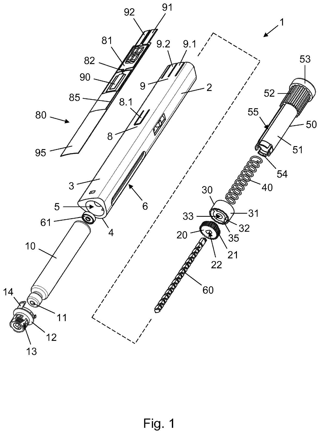
[0069]FIG. 1 is an exploded view of a pen injection device 1 according to an exemplary embodiment of the invention. The pen injection device 1 comprises a cylindrical housing 2 having a slightly curved information display surface 3 and a more conventionally curved opposing surface 4. The housing 2 accommodates a drug containing cartridge 10, which has been inserted through an opening 5 at a distal end thereof. The cartridge 10, which is closed at its distal end by a penetrable self-sealing septum 11 and at its proximal end by a slidable piston 15 (see FIG. 9), is held within t...


PUM


Abstract

The present invention provides a drug injection device (1) for delivering multiple doses of drug, comprising: a housing (2) extending along a main axis, a dose expelling mechanism comprising a piston rod (60) configured to move relative to the housing (2) from a first position to a second position to cause ejection of a dose of drug, the piston rod (60) extending between a proximal piston rod end and a distal piston rod end and comprising a dosing track (63), the piston rod (60) further being movable relative to the housing (2) from an initial pre-use position to a final end stop position to cause accumulated ejection of a predefined total dose, a dosing track follower (17) fixed with respect to the housing (2) and adapted to travel the dosing track (63) during dose ejection, a dose setting mechanism operable to set the dose to be ejected by the dose expelling mechanism, electronic means (82, 90, 91, 92, 95) for registering a dose setting operation and for registering a dose size of an ejected dose, and a display (81) adapted to indicate a size of a current set dose, the electronic means (82, 90, 91, 92, 95) being configured to provide a first type of update of the display (81) responsive to dose changing operations of the dose setting mechanism, wherein the electronic means (82, 90, 91, 92, 95) is further configured to calculate a current accumulated dose from the dose sizes of registered ejected doses to thereby provide an updated value of a total amount of drug ejected, determine a current remaining dose by comparing the current accumulated dose and the predefined total dose, and provide a second type of update of the display (81) when during a dose increasing operation of the dose setting mechanism the current set dose exceeds the current remaining dose, the second type of update being different from the first type of update, and wherein the final end stop position is defined by a track end configuration of the dosing track (63) between the proximal piston rod end and the distal piston rod end.

Description

CROSS-REFERENCE TO RELATED APPLICATIONS[0001]This application is a 35 U.S.C. § 371 National Stage application of International Application PCT / EP2018 / 058916 (published as WO 2018 / 185317), filed Apr. 6, 2018, which claims priority to European Patent Application 17165541.8, filed Apr. 7, 2017, the contents of all above-named applications are incorporated herein by reference.FIELD OF THE INVENTION[0002]The present invention relates generally to devices for administering medicine to a subject, and more specifically to injection devices capable of setting and expelling one or more doses of drug from a drug reservoir.BACKGROUND OF THE INVENTION[0003]In the diabetes care segment parenteral drug administration carried out using a traditional vial and syringe system is increasingly being substituted by administration using a pen injection device. Pen injection devices are particularly convenient in that they allow the user to perform a dosed injection from a prefilled drug reservoir without ...

Claims


Application Information

Patent Timeline
Patent Type & Authority Patents(United States)
IPC IPC(8): A61M5/315A61M5/31
CPCA61M5/31546A61M5/31593A61M2005/3126A61M5/31541A61M5/31551A61M5/31568A61M2005/3154A61M2205/502A61M2205/584
Inventor JAKOBSEN, NIKOLAJ EUSEBIUS
Owner NOVO NORDISK AS
Why Eureka
Try Eureka