Pressure Based Event Detection

a technology of event detection and pressure, applied in the direction of intravenous devices, other medical devices, infusion needles, etc., can solve the problems of insufficient patient compliance with established dosage intervals, improper dosage, and potential ill effects of such lack of compliance, so as to eliminate or reduce at least one drawback

Active Publication Date: 2018-07-12
NOVO NORDISK AS
View PDF1 Cites 0 Cited by
  • Summary
  • Abstract
  • Description
  • Claims
  • Application Information

AI Technical Summary

Benefits of technology

[0011]It is an object of the invention to eliminate or reduce at least one drawback of the prior art, or to provide a useful alternative to prior art solutions.
[0013]It is a further object of the invention to provide such a device which is simple to use and which is relatively inexpensive to produce.
[0014]It is an even further object of the invention to provide such a device which can be realised in a slender configuration that is particularly attractive for users carrying it around during the day.
[0028]The seal in the interface between the drug delivery unit and the cap may comprise a flexible tight-fitting structure, e.g. a sealing ring, arranged along an outer surface of the drug delivery unit, such as around a reservoir holder, and / or arranged along an inner surface of the cap, such as along an interior portion of the cap wall. The seal is adapted to at least substantially prevent air from entering the cavity between the cap wall and the drug delivery device, and therefore it contributes significantly to the generation of a steep, fleeting pressure gradient when the cap is dismounted from, or mounted onto, the drug delivery unit in conventional manner, i.e. in less than 5 seconds, for example in less than 4 seconds, in less than 3 seconds, in less than 2 seconds, in less than 1 second, or in less than half a second. Such a pressure gradient occurs over much shorter time than natural pressure changes experienced during e.g. plane ascension, car driving, or mountain climbing, and thus presents a credible indication of a cap mounting or dismounting action. The sealing ring may be a separate component mounted along an inner circumference of the cap, or along an outer circumference of the drug delivery unit, or it may be integrated into the cap, or onto the drug delivery unit, such as by 2 K moulding.
[0033]The predetermined period may be chosen in order to minimise the risk of registering false positives potentially arising from users more or less consciously manipulating the cap. In case the drug delivery device is an injection device as known from the diabetes care segment a proper use of the device will normally include the steps of cap dismounting, needle attachment, dose setting, needle insertion, dose expelling, needle retraction (and potentially removal), and cap re-mounting. Even the most experienced users need a certain amount of time to perform these steps. Hence, as one example, the predetermined period may be set to 10 seconds.
[0037]The above sketched drug delivery devices according to the present invention possess a number of advantages over the prior art solutions. For example, 1) the sensor device and the associated electronics can be placed independently in the cap and / or in the drug delivery unit, providing for great flexibility in the design of the drug delivery device, 2) the pressure detection system itself occupies very little space, and may therefore be placed so as to cause minimal impact on the size of the drug delivery device, such as in the cavity of the cap at the end wall. Hence, the only potential contributor to an increase in the radial dimension would be the seal between the cap and the drug delivery unit, 3) the pressure detection solution does not require a physical contact between electrical components and thus has no or only minimal influence on the geometries of the drug delivery unit and the cap as well as on whether an injection needle may be mounted on the drug delivery unit when the cap is attached, providing for a flexible device configuration, 4) the pressure detection system and the seal may be implemented solely in the cap, allowing the cap to be re-used with multiple drug delivery units, including drug delivery units with different medications, and 5) in case the drug delivery unit comprises a mounted injection needle when inserted in the cap the seal will reduce the drug evaporation and thereby the risk of needle clotting.

Problems solved by technology

Lack of substantial patient compliance with established dosage intervals has long been recognised as a major problem in treating illness.
Even a well-meaning and conscientious patient may frequently fail to take the medication at a desired time, and this may be the case even if the patient carries about the medication during the day.
Potential ill effects of such lack of compliance may be further compounded if the patient attempts to compensate for missed dosages by taking a larger dose at a later point in time.
Improper dosage may for example occur when the patient cannot precisely recall taking the medication and thus is unable to correctly judge how much time has elapsed since the last dose was absorbed.
People with diseases that require regular and systematic self-managed treatment regimes, such as e.g. diabetes, are constantly facing the challenge of remembering when to take their medicine.
However, especially for people who take medicine on a regular basis the act of dose administration itself may become so ingrained that they perform e.g. injections unconsciously and then later become unsure of whether they have actually received a particular dose.
This may potentially lead to dangerous double dosing incidents where the person ends up taking twice the recommended or calculated dose within a short time span.
If, for example, the user is in a hurry and fails to arrange the two entities in the exact relative position after a dose administration the related feature offered by the particular device will be compromised and the device rendered unreliable.
Furthermore, the arrangement of the control device as an exterior attachment to the cap in WO 02 / 056822, as well as the radially moving switch mechanism in WO 2012 / 001493, tends to lead to rather bulky caps, which are generally undesired by people who need to carry their drug delivery device around during the day.

Method used


Image

  • Pressure Based Event Detection
  • Pressure Based Event Detection
  • Pressure Based Event Detection

Examples


example

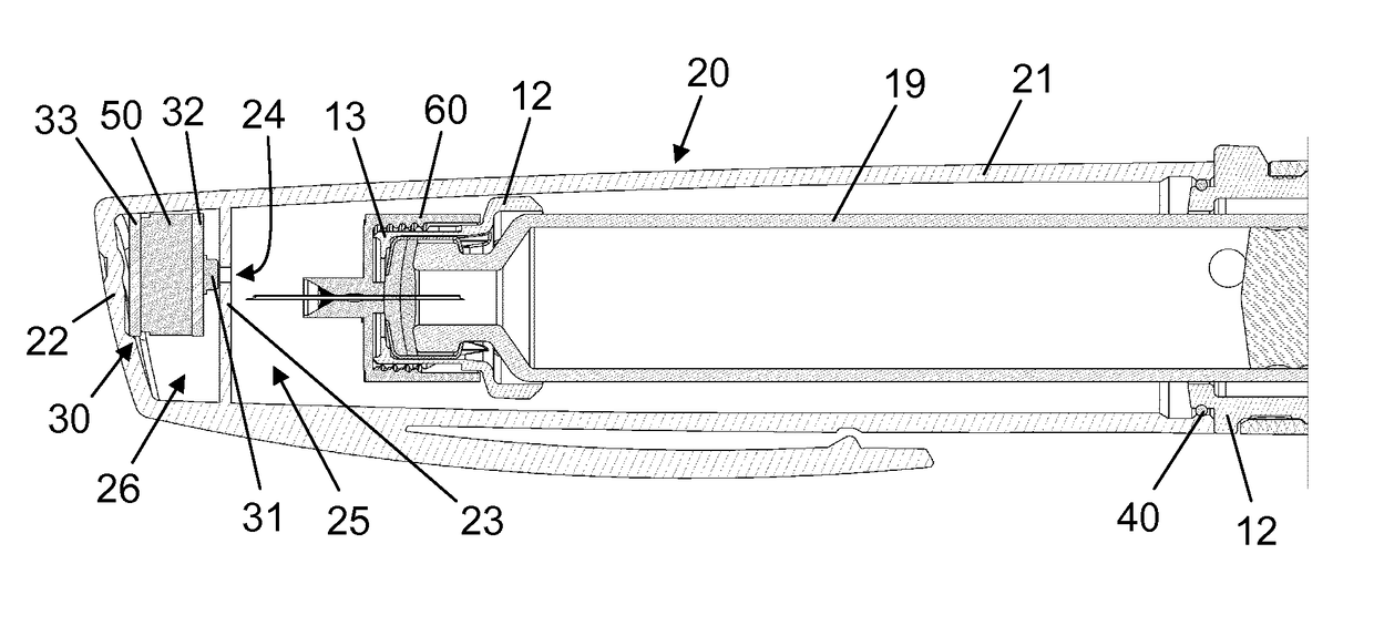
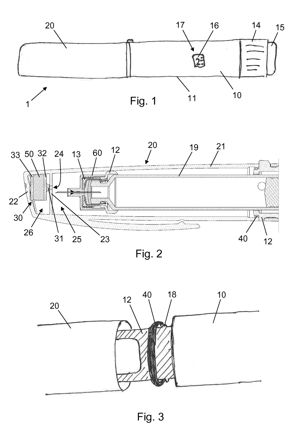
[0055]FIG. 4 is a graph which qualitatively illustrates the event logging functionality of the injection device 1. At time t=1 second a user pulls off the cap 20 from the injection pen 10. The action takes less than half a second and causes a fleeting local pressure drop of 20 mbar in both the proximal cavity 25 and the distal cavity 26 as the sealing ring 40 slides along the side wall 21. This pressure drop is detected by the sensor system 30, and since it fulfils both requirements of numerically exceeding the specified threshold level and taking less than 5 seconds it is registered as a cap off event. Subsequently, at time t=n seconds, the user puts the cap 20 back onto the injection pen 10. This action causes a fleeting local pressure rise of 80 mbar in both the proximal cavity 25 and the distal cavity 26 and is detected by the sensor system 30. Since the pressure rise fulfils both requirements of numerically exceeding the specified threshold level and taking less than 5 seconds ...


PUM


Abstract

The present invention provides a drug delivery device (1) comprising a drug delivery unit (10) comprising a dose expelling mechanism operable to expel a dose of drug from a drug reservoir (11), a cap (20) configured for dismountable mounting over a portion of the drug delivery unit (10), the cap (20) comprising a cavity (25, 26) for reception of the portion of the drug delivery unit (10), a seal (40) adapted to provide a sealing in an interface between the cap (20) and the drug delivery unit (10), a sensor system (30) configured to monitor internal pressure in the cavity (25, 26) and to register an event in response to sensing a change in the internal pressure which numerically exceeds a specified threshold level over a period of less than 5 seconds, and energy means (50) for powering the sensor system (30).

Description

FIELD OF THE INVENTION[0001]The present invention relates generally to drug delivery devices, and more specifically to such devices comprising a removable protective cap.BACKGROUND OF THE INVENTION[0002]Lack of substantial patient compliance with established dosage intervals has long been recognised as a major problem in treating illness. Typically, a physician will recommend a patient to take a needed drug according to a specified schedule, but the actual administration of the medicine is often left to the sole control of the patient. Even a well-meaning and conscientious patient may frequently fail to take the medication at a desired time, and this may be the case even if the patient carries about the medication during the day.[0003]Potential ill effects of such lack of compliance may be further compounded if the patient attempts to compensate for missed dosages by taking a larger dose at a later point in time. Improper dosage may for example occur when the patient cannot precisel...

Claims


Application Information

Patent Timeline
Patent Type & Authority Applications(United States)
IPC IPC(8): A61M5/32A61M5/20A61M5/315
CPCA61M5/3202A61M5/20A61M5/31548A61M5/24A61M2205/50A61M2205/3331
Inventor POULSEN, ULRIK DETLEF RAEDISCH
Owner NOVO NORDISK AS
Why Eureka
Try Eureka