
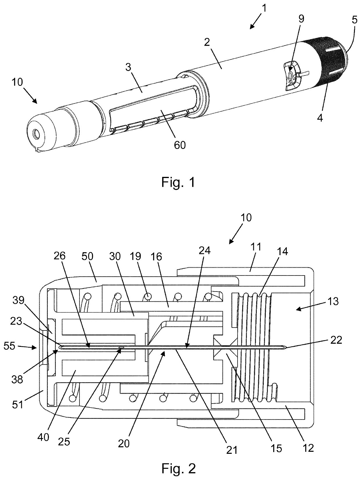
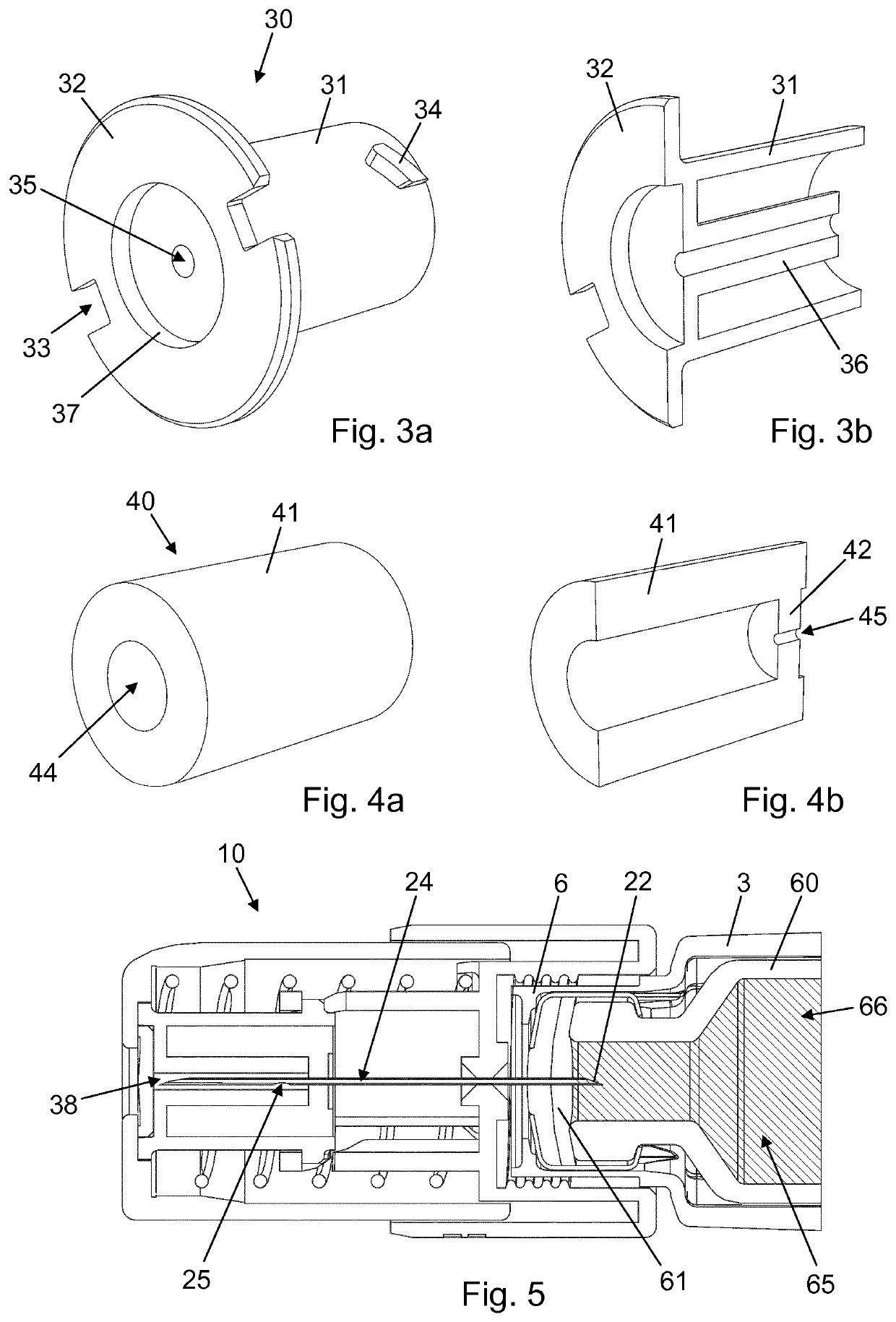
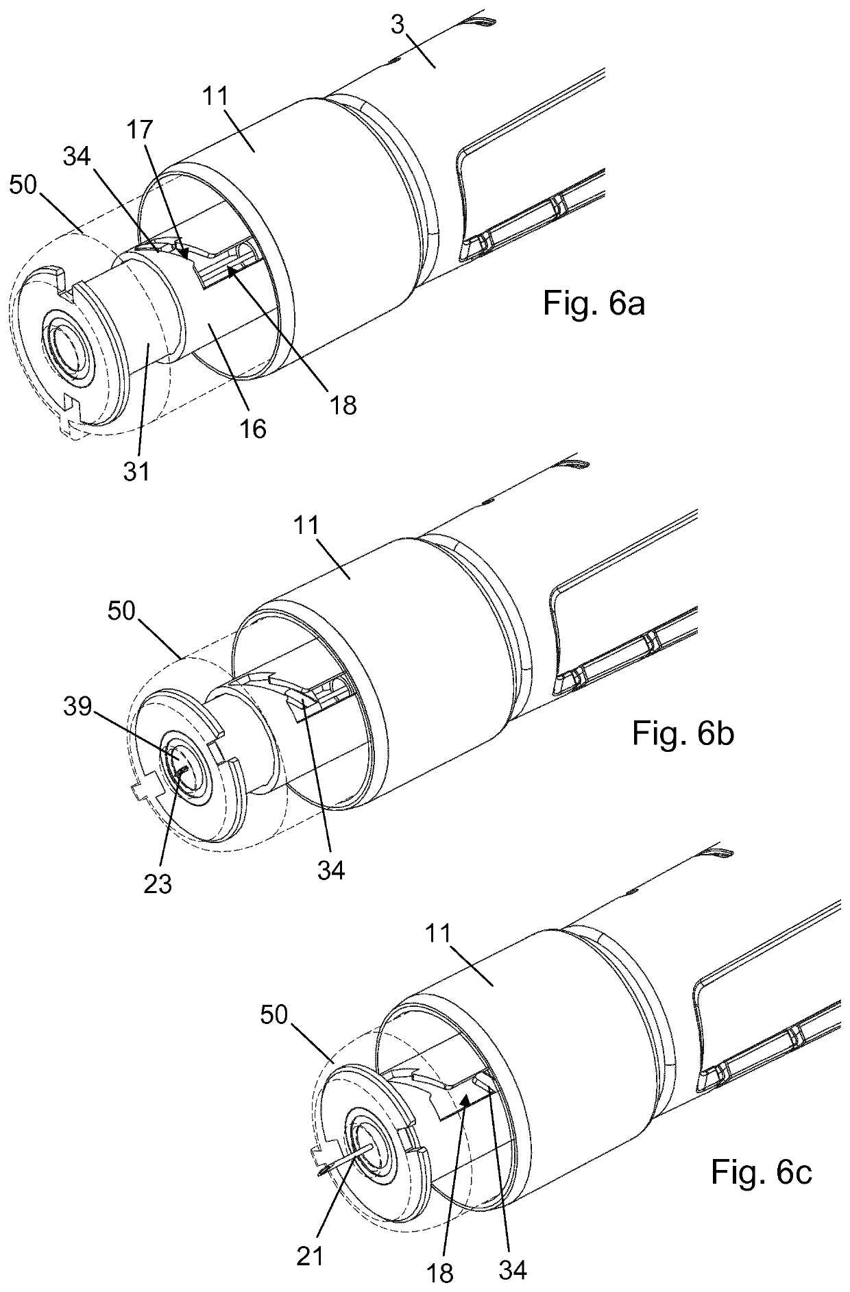
Needle unit with biostatic chamber

a biostatic chamber and needle technology, applied in the field of injection needles, can solve the problems of increasing the risk of both infections and needle stick injuries, cumbersome task of injection, and difficulty in preparing and removing the needle unit, so as to eliminate or reduce at least one drawback

Pending Publication Date: 2021-05-06
NOVO NORDISK AS
View PDF0 Cites 0 Cited by
  • Summary
  • Abstract
  • Description
  • Claims
  • Application Information

AI Technical Summary

Benefits of technology

The invention is a needle unit for a drug delivery device that can be used safely for multiple times. It also provides a simple and cost-effective way to create a biostatic environment for the needle. This helps to prevent infection and other drawbacks associated with needle reuse.

Problems solved by technology

The readying and subsequent removal of the needle unit is both the most complicated and the most time consuming part of the injection procedure.
Especially for young and elderly users the handling of the small items and foils can present a challenge and make the task of injection a bit cumbersome.
As a result, some users reuse the needle unit several times. In fact, some users only change the needle unit when the injection device is empty or if the needle for example exhibits clogging or hooking.
However, it also entails increased risks of both infections and needle stick injuries, the former due to needle contamination and the latter due to the users typically disposing of the original needle unit packaging in connection with the fitting of the needle and therefore do not have this available as receptacle for when they change the needle unit after several times of reuse.
While this needle unit concept allows for safe multiple reuses the various embodiments pre-sented in WO 2015 / 062845 require either proximal movement of a reservoir wall against the force of a dedicated spring component or proximal movement of the cartridge body relative to the piston in order to fill the reservoir, adding to the complexity and cost of the injection device / needle unit system.
Furthermore, since the reservoir is filled only once but the needle unit is intended for multiple reuses, e.g. over a time period of several weeks, the microbe-hostile environment in the reservoir may degrade due to evaporation of components of the preservatives in the preservative containing liquid.

Method used


Image

  • Needle unit with biostatic chamber
  • Needle unit with biostatic chamber
  • Needle unit with biostatic chamber

Examples


first embodiment

[0090]The chamber structure 230 has an outer cylindrical wall 231, identical to the outer cylindrical wall 31 of the first embodiment, and an inner wall 236. The inner wall 236 has a cylindrical exterior surface around which the sealing sleeve 240 is fitted, in a manner similar to the above described, but is of varying thickness, which provides a sealed chamber 238 having a distal cylindrical zone 236a of a first diameter, a proximal cylindrical zone 236c of a second diameter, being larger than the first diameter, and an intermediate conical zone 236b bridging the distal cylindrical zone 236a and the proximal cylindrical zone 236c.

[0091]This third embodiment presents an alternative way of obtaining substantially the same fill level of the sealed chamber 238 as that of the sealed chamber 138 according to the second embodiment. The effect of the three chamber zones is similar to that of the skewed side hole 125, i.e. liquid drug 266 flowing through the proximal flow channel 224 enter...

fourth embodiment

[0105]In a pre-use state of the needle unit 410 the injection needle 420 extends through the sealing sleeve 440 and a distal portion of the needle tube 421, including the distal needle end 423, resides within the sealed chamber 438 which is otherwise filled with air. The needle tube 421 is provided with a distal side hole 425 and a proximal side hole 427, and the lumen of the needle tube 421 is therefore divided into a proximal flow channel 424, leading from the proximal needle end 422 to the proximal side hole 427, and a distal flow channel 426, leading from the distal side hole 425 to the distal needle end 423. However, in contrast to the invention, the lumen of the needle tube 421 between the proximal side hole 427 and the distal side hole 425 comprises a block 429 which prevents fluid flow through the needle tube 421 between the proximal side hole 427 and the distal side hole 425.

[0106]The axial distance between the distal side hole 425 and the proximal side hole 427 is correlat...

sixth embodiment

[0112]FIG. 13 is an exploded, partly longitudinally sectioned, view of a chamber sub-assembly 590 as used in a needle unit 510 (ref. FIG. 14) according to the invention. The chamber sub-assembly 590 comprises a needle hub 515 and a hub support 575 comprising a hub carrier 576 with a circumferential protrusion 577 configured to engage with a circumferential groove 599 in the needle hub 515 to thereby axially fixate the needle hub 515 in the hub support 575.

[0113]The needle hub 515 has a through-going bore 598, in which an inlet needle 580 is fixedly mounted, and a seat 597 for reception and retention of an injection needle 520. The inlet needle 580 comprises an inlet needle tube 581 which has a pointed proximal inlet needle end 582 configured for penetration of a drug reservoir septum and a distal inlet needle end 583. The inlet needle tube 581 extends axially through the hub carrier 576, and the proximal inlet needle end 582 is thus positioned proximally of the hub support 575 while...


PUM


Abstract

The present invention provides a needle unit (10, 310, 410, 510) having a proximal space (13, 513) adapted to accommodate a portion of a variable volume reservoir, the needle unit (10, 310, 410, 510) comprising: a needle carrier (15, 315, 415, 515), a needle tube (21, 121, 221, 321, 421, 521) being fixed to the needle carrier (15, 315, 415, 515) and comprising a distal needle end (23, 123, 223, 323, 423, 523) for providing fluid communication to an injection site, a needle shield (50, 350, 450, 550) carrying a sealed chamber (38, 138, 238, 338, 438, 538) for accommodating a distal portion of the needle tube (21, 121, 221, 321, 421, 521), the sealed chamber (38, 138, 238, 338, 438, 538) being sealed distally by a penetrable self-sealing septum (39, 139, 239, 339, 439, 539), and a flow channel (24, 124, 224, 324, 424, 524) for establishing fluid communication between the sealed chamber (38, 138, 238, 338, 438, 538) and the proximal space (13, 513), wherein the needle shield (50, 350, 450, 550) and the needle carrier (15, 315, 415, 515) are capable of relative motion between a first relative position in which the sealed chamber (38, 138, 238, 338, 438, 538) houses the distal needle end (23, 123, 223, 323, 423, 523), and a second relative position in which the distal needle end (23, 123, 223, 323, 423, 523) protrudes from the sealed chamber (38, 138, 238, 338, 438, 538) through the penetrable self-sealing septum (39, 139, 239, 339, 439, 539), and wherein the needle tube (21, 121, 221, 321, 421, 521) further comprises a side hole (25, 125, 225, 325, 425, 525), the side hole (25, 125, 225, 325, 425, 525) being in fluid communication with the flow channel (24, 124, 224, 324, 424, 524) and positioned within the sealed chamber (38, 138, 238, 338, 438, 538) when the needle shield (50, 350, 450, 550) and the needle carrier (15, 315, 415, 515) are in the second relative position.

Description

FIELD OF THE INVENTION[0001]The present invention relates generally to medical devices and more particularly to injection needles for use with drug delivery devices.BACKGROUND OF THE INVENTION[0002]Injection systems for self-administering of drugs comprising a pen injection device and an attachable pen needle unit have become increasingly popular due to generally simple and convenient handling patterns. Users of such injection systems are recommended to discard the needle unit after a single injection to minimise the risk of contamination. Hence, in the course of its lifetime the injection device is by default used with multiple needle units.[0003]Needle units are typically wrapped and sealed individually to ensure sterility prior to use. In connection with a dose administration action the user must therefore unwrap the needle unit, mount it on the injection device, perform the injection, dismount it from the injection device, re-wrap or otherwise encapsulate it to prevent needle st...

Claims


Application Information

Patent Timeline
IPC IPC(8): A61M5/00A61M5/32A61M5/34
CPCA61M5/001A61M5/326A61M2005/3117A61M5/3291A61M5/34A61M5/31A61M5/3271A61M5/3298A61M2005/3267
Inventor BENGTSSON, HENRIKGLENTING, VERA PINTOKVOLSBJERG, BOJENSEN, BRIAN
Owner NOVO NORDISK AS
Learn More