
Sensor receptacle for receiving a sensor of a motor vehicle and a trim component of a motor vehicle with such sensor receptacle

a technology for motor vehicles and sensor receptacles, which is applied in the direction of superstructure subunits, electric/fluid circuits, instruments, etc., can solve problems such as affecting the functionality of sensors

Active Publication Date: 2022-08-02
MOTHERSON INNOVATIONS CO LTD
View PDF14 Cites 0 Cited by
  • Summary
  • Abstract
  • Description
  • Claims
  • Application Information

AI Technical Summary

Benefits of technology

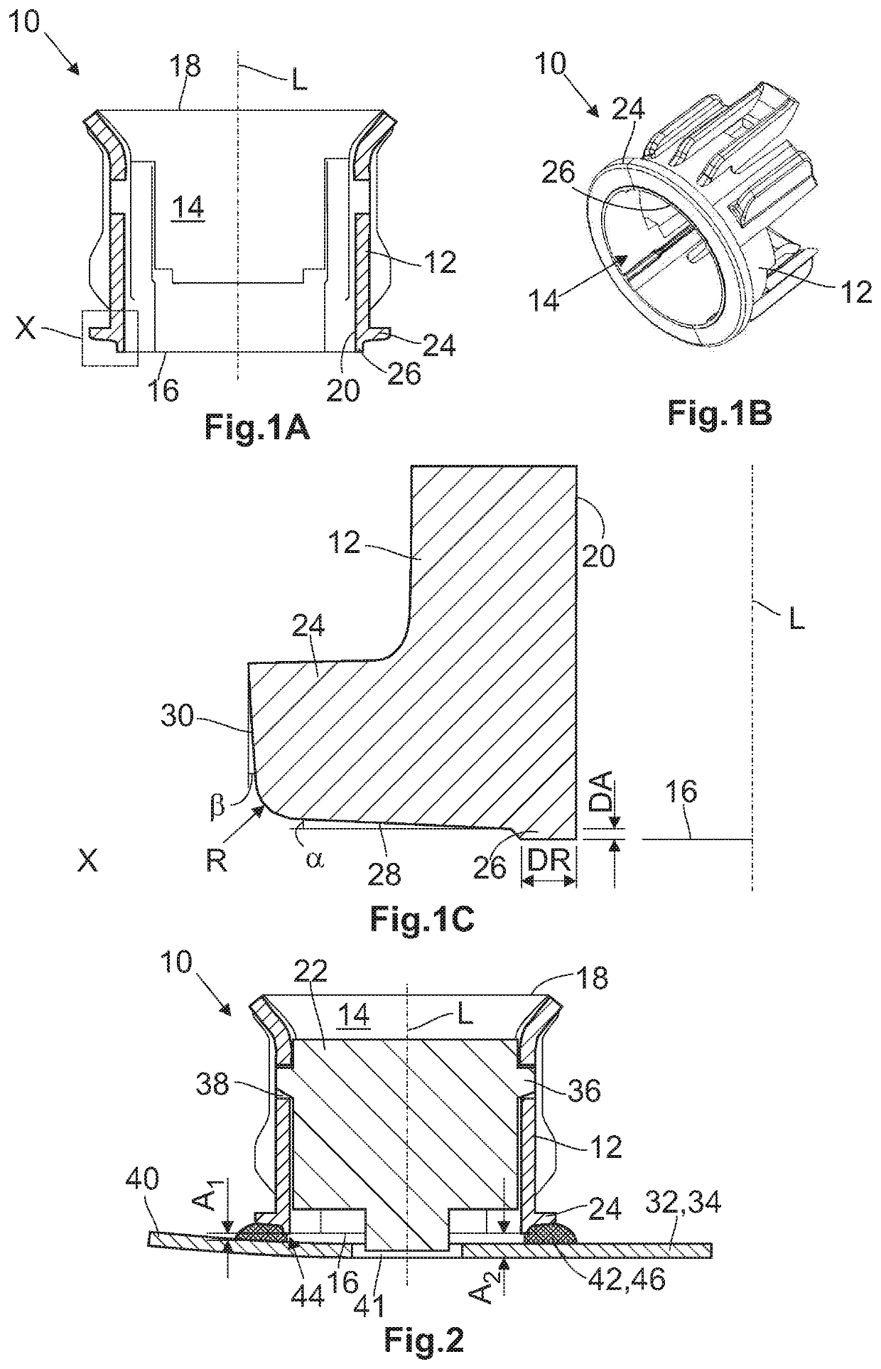
[0014]The sensor receptacles disclosed in EP 3 118 065 A1 have in part joining flanges which however are not provided with protrusions extending along the longitudinal axis. In contrast, the proposed sensor receptacles have such protrusions, which are arranged on the joining flanges and operate as a kind of flow straightener. Consequently, the protrusions displace the liquid filling and fastening agent away from the cavity when the sensor receptacle is connected with the trim component. This prevents the filling and fastening agent from entering the cavity and there potentially impairing the functionality of the sensors. But at a minimum, the amount of the filling and fastening agent entering the cavity is reduced compared to the sensor receptacles disclosed in EP 3 118 065 A1 by so much that the filling and fastening agent reaching the cavity and cured in the cavity does not interfere with the function of the sensor.
[0032]According to another embodiment, the adhesive can be cured by exposure to electromagnetic radiation of a wavelength between 350 nm and 450 nm. The wavelength between 350 nm and 450 nm produces light with a violet-blue color that is visible to the human eye. In this way, on the one hand, the operability of the radiation source can be readily determined and, on the other hand, the electromagnetic radiation in this wavelength range contains sufficient radiant energy to initiate curing of the filling and fastening agent.

Problems solved by technology

This prevents the filling and fastening agent from entering the cavity and there potentially impairing the functionality of the sensors.

Method used


Image

  • Sensor receptacle for receiving a sensor of a motor vehicle and a trim component of a motor vehicle with such sensor receptacle

Examples


Embodiment Construction

[0038]Throughout all the Figures, same or corresponding elements are generally indicated by same reference numerals

[0039]Turning now to the drawing and particularly FIG. 1A, there is shown an embodiment of a sensor receptacle 10 according to the present invention in a schematic sectional view. The sensor receptacle 10 includes a wall 12, which encloses a cavity 14 and defines a longitudinal axis L of the sensor receptacle 10. The cavity 14 has a first opening 16 and a second opening 18. The first opening 16 and the second opening 18 delimit the sensor receptacle 10 in the axial direction.

[0040]As is evident in particular from the FIG. 1B, which shows the sensor receptacle 10 illustrated in FIG. 1A in a perspective view, the sensor receptacle 10 is substantially tubular, so that the cavity 14 has an approximately cylindrical shape and forms an interior surface 20.

[0041]The cavity 14 expands toward the second opening 18, allowing a sensor 22 (see FIG. 2) to be introduced into the cavi...


PUM


Abstract

A sensor receptacle for receiving a sensor of a motor vehicle is disclosed. The receptacle includes a wall enclosing a cavity with a first opening and a second opening and which defines a longitudinal axis (L), wherein the sensor can be introduced into the cavity by a movement along the longitudinal axis (L) through the first opening and / or through the second opening. A joining flange is arranged in the region of the first opening and the sensor receptacle is connected by way of the joining flange to a trim component of the motor vehicle by forming a cavity between the sensor receptacle and the trim component, such that the sensor receptacle can be connected to the trim component by way of a filling and fastening agent that fills the cavity, and wherein a protrusion is arranged on the joining flange and extending along the longitudinal axis (L). The joining flange and the protrusion are formed such that the filling agent is displaced away from the cavity when connecting the sensor receptacle with the trim component.

Description

CROSS-REFERENCES TO RELATED APPLICATIONS[0001]This application claims the priority of European Patent Application, Serial No. 18 208 335.2, filed Nov. 26, 2018, pursuant to 35 U.S.C. 119(a)-(d), the disclosure of which is incorporated herein by reference.BACKGROUND OF THE INVENTION[0002]The present invention relates to a sensor receptacle for receiving a sensor of a motor vehicle. Furthermore, the invention relates to a trim component of a motor vehicle with such a sensor receptacle.[0003]Many motor vehicles have assistance systems which assist the driver in the operation of the motor vehicle. An example of such assistance systems are parking aids (PDC: Park Distance Control), wherein the driver receives a visual and / or acoustic message about the remaining distance to an object in the vicinity of the motor vehicle when parking, so that the driver can prevent a collision with the object and thus damage to the motor vehicle and to the object while simultaneously making optimum use of ...

Claims


Application Information

Patent Timeline
Patent Type & Authority Patents(United States)
IPC IPC(8): B60R13/02B60R16/03G01S7/03G01S7/521G01S7/02
CPCB60R13/02B60R16/03B60R2013/0287G01S7/027G01S7/03G01S7/521B60R19/483G01S15/931G01S2015/938
Inventor WALZ, JOCHEN
Owner MOTHERSON INNOVATIONS CO LTD
Learn More