
Spring device for disc brake, pad spring and disc brake assembly

a technology of disc brake and spring, which is applied in the direction of brake types, slack adjusters, braking elements, etc., can solve the problems of generating residual braking torque and annoying noise, more frequent maintenance, and undesired wear of pads and brake discs

Active Publication Date: 2022-08-02
FRENI BREMBO SPA
View PDF17 Cites 3 Cited by
  • Summary
  • Abstract
  • Description
  • Claims
  • Application Information

AI Technical Summary

Benefits of technology

The solution effectively reduces noise and residual braking torque, maintains compact dimensions, and simplifies assembly, providing a quiet and efficient braking action while minimizing maintenance needs.

Problems solved by technology

During the step of releasing of the braking, the at least one piston ceases to apply the thrust action, but the pad which is in contact with the braking band tends to remain in place, whereby generating a residual braking torque and an annoying noise, which can be perceived also by the vehicle users.
Such a residual braking torque causes an undesired wear of the pads and of the brake disc, which implies more frequent maintenance for their replacement, and minimum fuel consumption for feeding the drive unit with the energy, even if minimum, needed to overcome this residual torque.
This solution, although advantageous from some points of view, does not fully solve the problem, and indeed imposes strict manufacturing tolerances of the undercut niches of the pad plate, in order to allow the spring arms to apply the required elastic biasing action on the pad.
Furthermore, such a solution, given the poor accessibility of the undercut niches formed by the horns of the plate, results in a complicated assembly of the pad on the spring and of the spring and pad assembly to the caliper body.
A thus made spring necessarily has an undesirable dimension in radial direction, which contrasts with the need to make discs of increasingly greater diameter which impose a radial space reduction in the wheel rim for the brake caliper housing.
The need is further felt to provide a spring device and a pad and spring assembly solution which is compact without because of this resulting in a poor anti-knock action.

Method used


Image

  • Spring device for disc brake, pad spring and disc brake assembly
  • Spring device for disc brake, pad spring and disc brake assembly
  • Spring device for disc brake, pad spring and disc brake assembly

Examples


Embodiment Construction

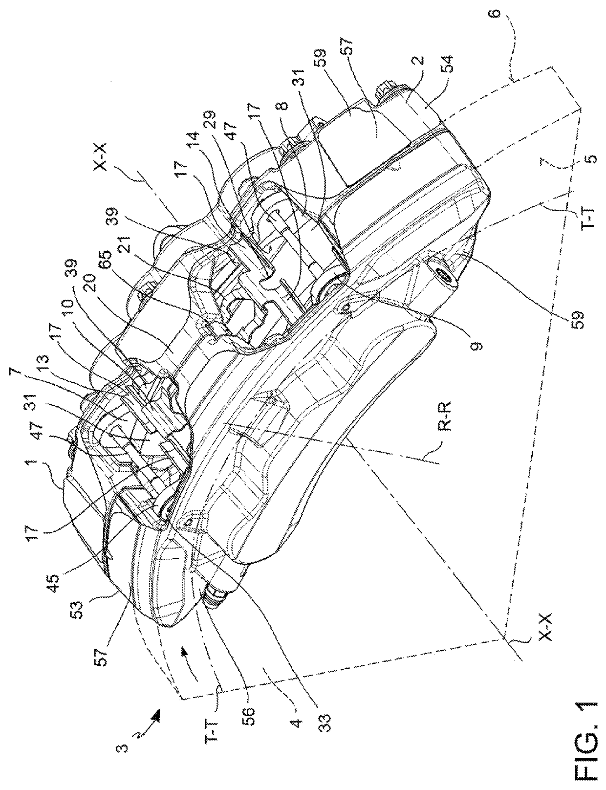
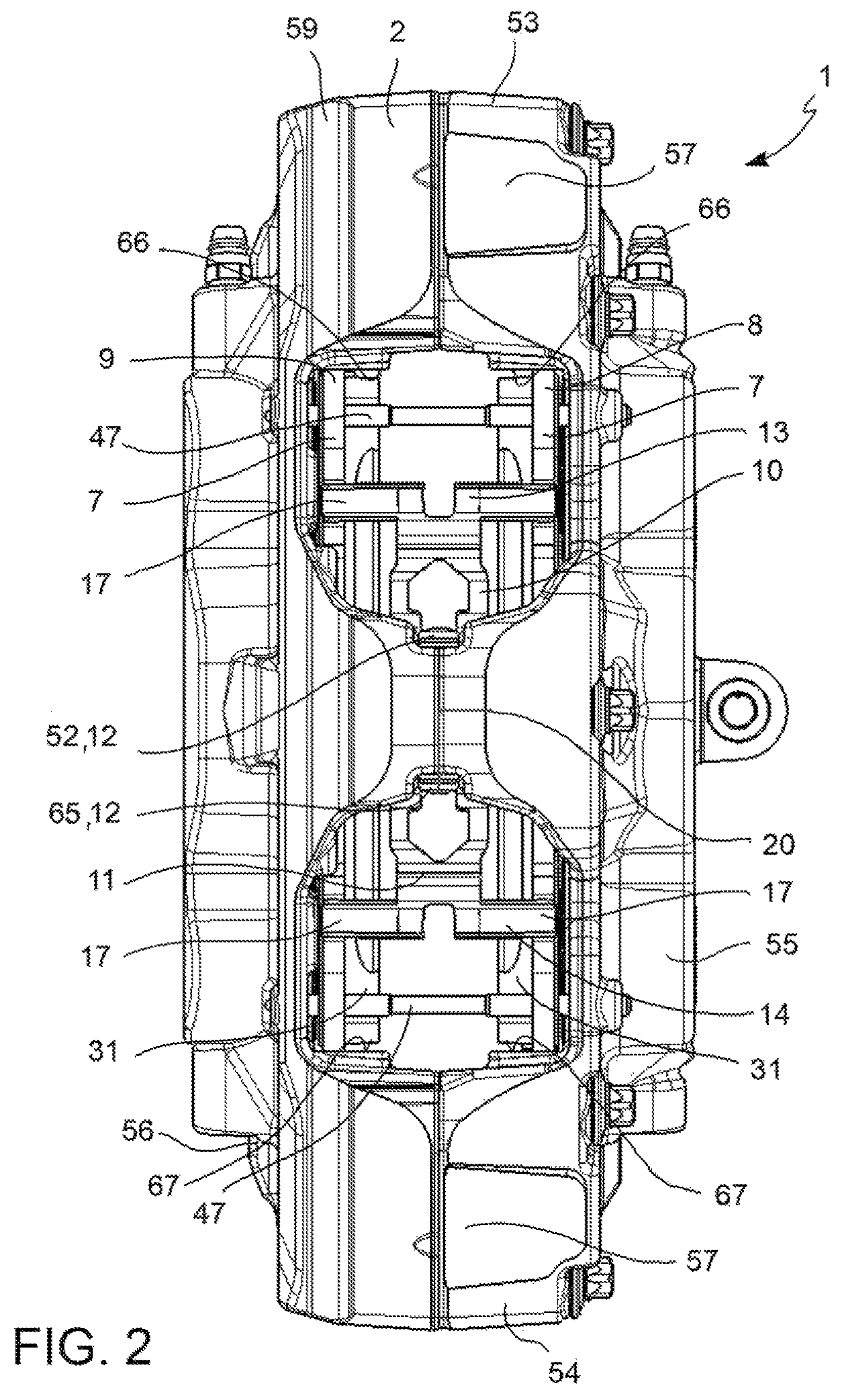
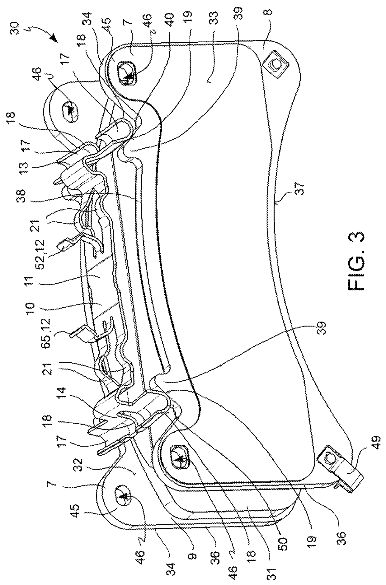
[0033]According to a general embodiment, a spring device 10 for a disc brake 3 is provided.

[0034]Said disc brake comprises a disc 4 and a brake caliper 1 having a caliper body 2 adapted to straddle the disc 4 and at least one brake pad 8, 9 adapted to press against a facing braking surface 5, 6 of the disc 4 when biased by thrust means, e.g. a cylinder-piston assembly, of the brake caliper 1.

[0035]Said disc brake 3 defines an axial direction X-X either parallel to or coinciding with the rotation axis of the disc 4, a radial direction R-R orthogonal to the axial direction X-X, and a tangential T-T or circumferential direction T-T, orthogonal to both the axial direction X-X and to the radial direction R-R. A radially inner direction, or radially inner direction RI, directed in radial direction R-R towards the rotation axis of the disc 4, and an opposite radially outer direction, or outer radial direction RE, are also defined. Said axial X-X, radial R-R, radial inner RI, radial outer R...


PUM


Abstract

A spring device for a disc brake, a pad and spring assembly for a disc brake, a brake caliper, and a disc brake is described. The spring device may have a spring body having prevalently longitudinal development, with at least one coupling portion, to couple in a snapping manner the spring device to a portion of an associable brake caliper in a removable manner. The spring pad assembly may have at least one brake pad having at least one ramp surface, inclined with respect to the radial direction and to the tangential direction, which forms an abutment reference for the at least one thrust surface of the spring device. The at least one ramp surface of the support plate puts in traction the spring device.

Description

FIELD OF THE INVENTION[0001]The present invention relates to a spring device for disc brake, a pad and spring assembly for a disc brake, a brake caliper, and a disc brake.BACKGROUND ART[0002]The brake caliper of a disc brake is generally arranged straddling the outer peripheral margin of a brake disc, adapted to rotate about a rotational axis defining an axial direction (X-X). In a disc brake, a radial direction (R-R), which is substantially orthogonal to said axial direction (X-X), and a tangential or circumferential direction (T-T), orthogonal to both said axial direction (X-X) and said radial direction (R-R), is further defined. Brake pads generally comprise a pad onto which a friction material is fixed, adapted to press against a facing braking surface of the braking band of the brake disc. The aforesaid axial (X-X), radial (R-R) and tangential (T-T) or circumferential (T-T) directions are understood as defined on a brake pad, even when it is considered alone.[0003]As known, opp...

Claims


Application Information

Patent Timeline
Patent Type & Authority Patents(United States)
IPC IPC(8): F16D65/40F16D65/097F16D55/226F16D65/00F16D55/00
CPCF16D65/0977F16D55/226F16D65/0056F16D65/0068F16D2055/0016F16D55/224F16D55/228
Inventor D'ALESSIO, DAVIDECOSTA, MATTEOLONGHI, DANIEL
Owner FRENI BREMBO SPA
Learn More