Parallel multi-region imaging device

a multi-region imaging and parallel technology, applied in the field of imaging, can solve the problems of inability to receive the detector, no tomography capability, and fast acquisition of parallel information

Active Publication Date: 2022-08-09
HUAZHONG UNIV OF SCI & TECH
View PDF31 Cites 0 Cited by
  • Summary
  • Abstract
  • Description
  • Claims
  • Application Information

AI Technical Summary

Benefits of technology

[0019]To sum up, compared with the prior art, the above technical solution conceived by the present invention can achieve following beneficial effects: the multi-focus generation module is used to generate multiple different illumination regions on the object space, so as to generate multiple paths of signal light. The spatial demodulation module is used to make spatial energy distribution of each path of signal light finally no longer overlap (or only have little overlap). The detection module is used to detect signals, thereby solving the technical problems of difficulty in weak light detection, incapability of signal demodulation, high proneness to misjudgment and the like in the existing parallel multi-region imaging detection technique.

Problems solved by technology

This way of acquiring information in parallel is fast (up to several thousand frames per second), but has no tomography capabilities.
Although some other regions outside the object point still have certain intensity of illumination light, signals sent by these positions cannot pass through the pinhole after passing through the imaging system, and cannot be received by the detector, thereby being blocked.
Both of the above imaging techniques with tomography capabilities require scanning imaging, and scanning one surface or even a solid in space is time consuming.
Even with high-speed scanners, since exposure is performed on points in space in a serial mode, the single-point exposure time is very limited, which is detrimental to signal intensity and a signal-to-noise ratio.
Parallel detection on spatial regions of different axial positions is difficult due to a reason of the object-image relationship.
Although several methods for parallel detection on spatial regions of different axial positions have been developed in the industry, the limitations are large.
The limitations of this method are: firstly, the method requires a high-speed signal acquisition system, because the gain-bandwidth product of a signal amplifier is limited, the high speed means a large bandwidth, resulting in small gain and difficulty in detecting weak light; and secondly, the sample needs to have a fast response to the illumination light, when the sample is a fluorescent sample, some of the fluorescent substances have a long fluorescence lifetime, which causes aliasing of the signals at different positions in time and further causes incapability of demodulation.
The limitations of this method are as follows: firstly, it needs enough prior knowledge about the sample; and secondly, the signals in the space need to be sparse, and if the signals are relatively dense in space, the algorithm is prone to misjudgment.

Method used


Image

  • Parallel multi-region imaging device
  • Parallel multi-region imaging device
  • Parallel multi-region imaging device

Examples


Embodiment Construction

[0036]In order to make the objects, technical solutions and advantages of the present invention more clear, the present invention will be further described in detail below with reference to the accompanying drawings and embodiments. It should be understood that the specific embodiments described herein are merely illustrative of the present invention and are not intended to limit the present invention. Further, the technical features involved in the various embodiments of the present invention described below may be combined with each other as long as they do not constitute a conflict with each other.

[0037]The present invention relates to a device for implementing parallel multi-region imaging using a certain structure. The imaging of the present invention refers to acquiring optical information in space.

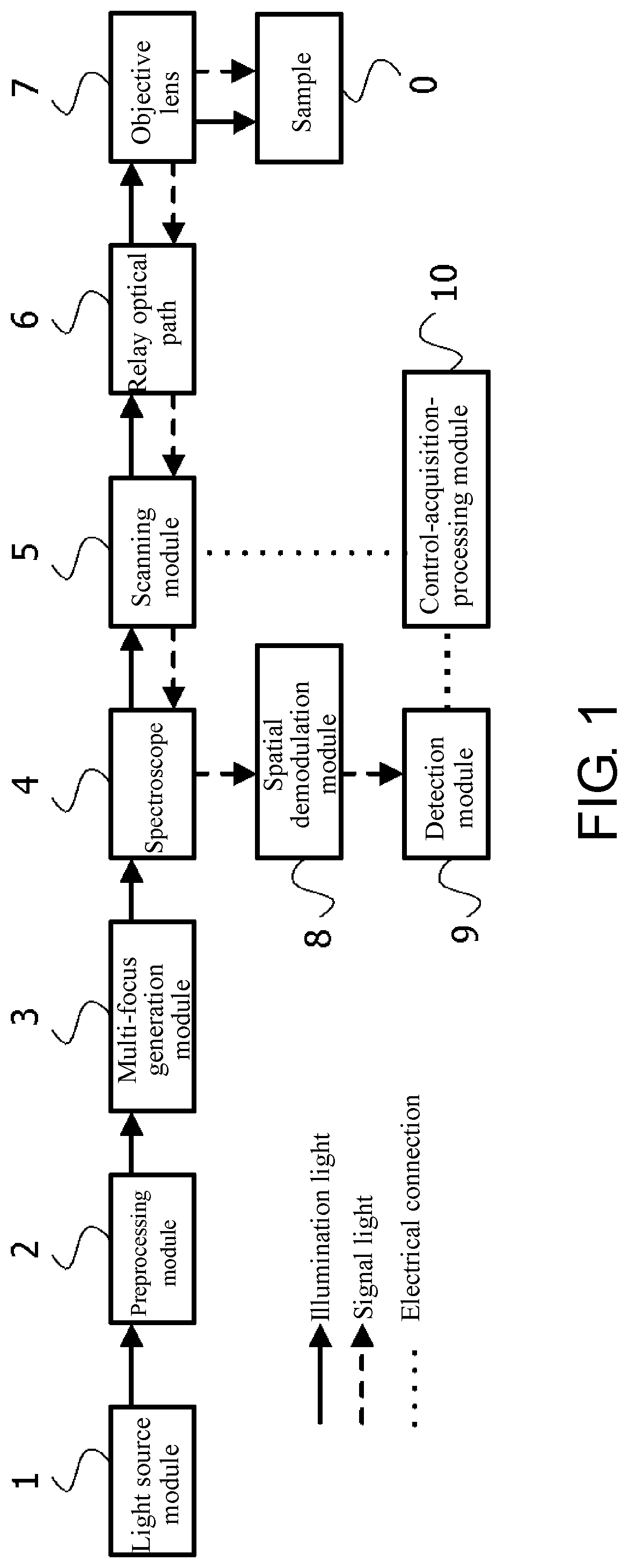
[0038]FIG. 1 shows a structure diagram of a device according to an embodiment of the present invention, including a light source module 1, a preprocessing module 2, a multi-focus ge...


PUM


Abstract

The parallel multi-region imaging device includes a multi-focus generation module, a spatial demodulation module, and a detection module. The multi-focus generation module is configured to modulate illumination light to generate a plurality of focuses in an object-side, and to form a plurality of different illumination regions, thereby generating multiple paths of signal light through a sample to be imaged. The spatial demodulation module is configured to make spatial energy distribution of each path of signal light no longer overlap or make an overlapping region smaller than a target requirement. The detection module is configured to independently detect each path of signal light passing through the spatial demodulation module, so as to implement parallel multi-region imaging.

Description

CROSS-REFERENCE TO RELATED APPLICATION[0001]This is a 371 application of the International PCT application serial no. PCT / CN2018 / 106072, filed on Sep. 18, 2018, which claims the priority benefits of China Application No. 201810937498.2 filed on Aug. 17, 2018. The entirety of each of the above-mentioned patent applications is hereby incorporated by reference herein and made a part of this specification.BACKGROUND OF THE INVENTION1. Field of the Invention[0002]The present invention belongs to the field of imaging, and more particularly relates to a parallel multi-region imaging device.2. Description of Related Art[0003]Imaging techniques are used to acquire spatial information of a sample. A wide-field imaging technique uses area array detection that can acquire optical information in an imaged region at an exposure time, and is a way of acquiring information in parallel. This way of acquiring information in parallel is fast (up to several thousand frames per second), but has no tomog...

Claims


Application Information

Patent Timeline
Patent Type & Authority Patents(United States)
IPC IPC(8): G02B21/00G02B21/02H04N5/225
CPCG02B21/0032G02B21/008G02B21/0036G02B21/02H04N5/2256G02B21/0052H04N23/56
Inventor LV, XIAOHUAZENG, SHAOQUNHU, QINGLEILI, PEI
Owner HUAZHONG UNIV OF SCI & TECH
Why Eureka
Try Eureka