Airtight terminal

a terminal and airtight technology, applied in the direction of insulated conductors, coupling device connections, cables, etc., can solve the problems of difficult to secure an adequate space for the installation of electric compressors, and achieve the effects of reducing the need for gaskets, and simplifying the assembly process of electric compressors

Active Publication Date: 2022-08-16
SCHOTT JAPAN CORP
View PDF58 Cites 0 Cited by
  • Summary
  • Abstract
  • Description
  • Claims
  • Application Information

AI Technical Summary

Benefits of technology

[0008]According to the present invention, an airtight terminal includes a metallic outer ring having a sealing hole, a lead inserted through the sealing hole in the metallic outer ring, and an insulating material to hermetically seal a gap between the metallic outer ring and the lead, is provided, wherein the metallic outer ring has a seal coat put on a surface of the metallic outer ring coming into contact with an external device. The surface coming into contact with the external device, described herein, refers to a contact surface of the metallic outer ring that comes into contact with an external device such as an airtight container to hermetically fix the airtight terminal to the external device. The seal coat is fixed or attached to the metallic outer ring. Since the seal coat is put on the contact surface coming into contact with the external device, fastening the airtight terminal to the airtight container ensures airtightness for the contact surface. This allows only the airtight terminal to be directly attached to a pressure vessel housing an electric compressor. According to the present invention, unlike the conventional airtight terminal, it becomes unnecessary to install a metal gasket. Hence, the present invention contributes to simplify an assembly process for electric compressors and reduce a number of components, thus an economic effect can be obtained.

Problems solved by technology

This poses a problem especially at extremely cold or extremely hot places, in summer or winter.
This has created a situation in which it is difficult to secure an enough space for installation of the electric compressor in the engine room.

Method used


Image

  • Airtight terminal
  • Airtight terminal
  • Airtight terminal

Examples


examples

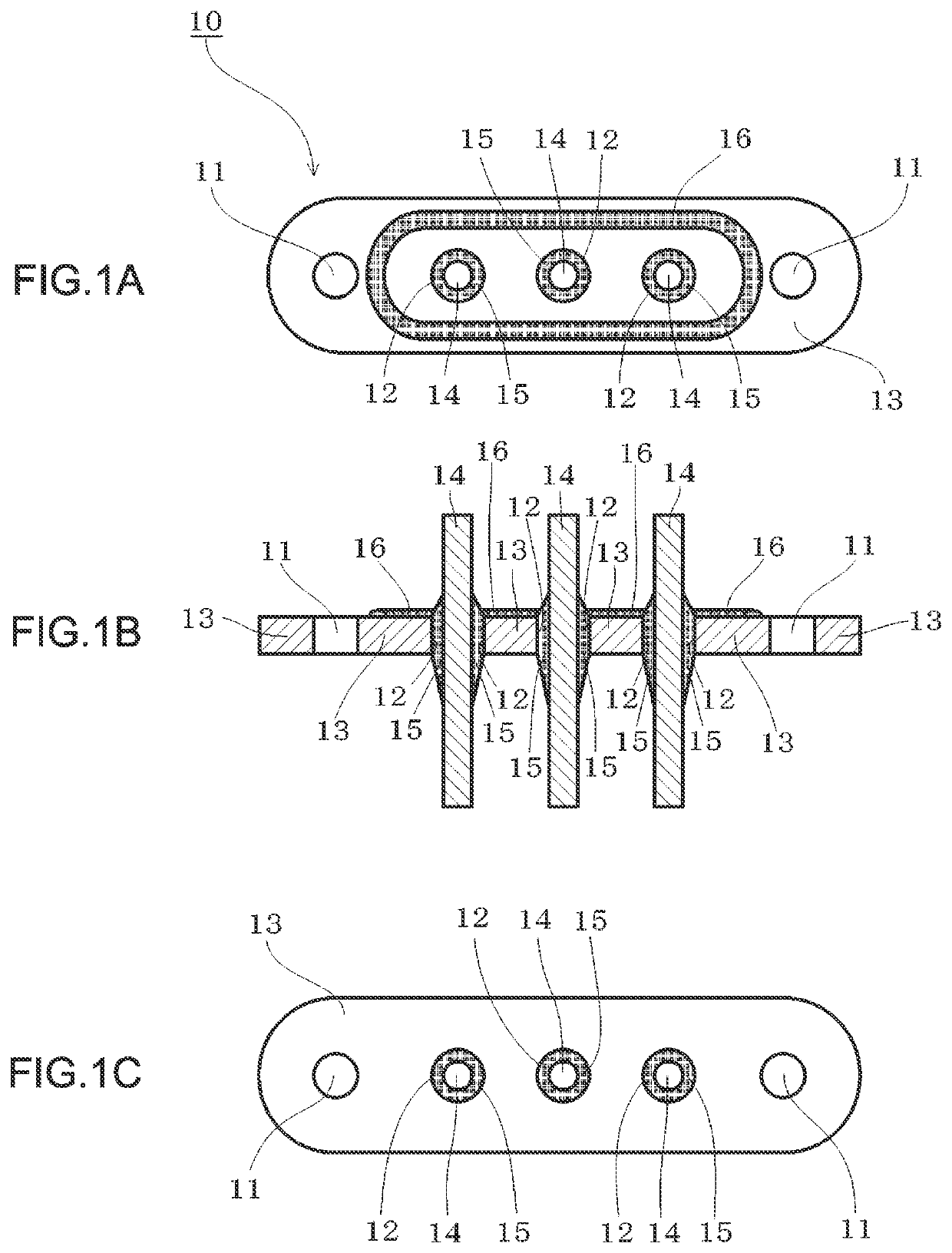
[0037]As illustrated in FIGS. 1A, 1B and 1C, an airtight terminal 10 of Example 1 according to the present invention includes a metallic outer ring 13 made of carbon steel, a plurality of leads 14 made of an Fe—Cr iron-base alloy, and insulating materials 15 made of soda barium glass to seal gaps between the metallic outer ring 13 and the respective leads 14. The metallic outer ring 13 has a plurality of through holes 11 formed for screw fastening and a plurality of sealing holes 12 arranged linearly. The leads 14 are inserted through the sealing holes 12 in the metallic outer ring 13. The metallic outer ring 13 has a seal coat 16 made of silicone rubber on an upper surface of the metallic outer ring 13 that is a contact surface to which an external device is attached. The seal coat 16 is put in a shape of an oval embankment, and all the sealing holes 12 are disposed inside a region surrounded with the embankment shape. The airtight terminal 10 is fastened to the external device wit...


PUM


Abstract

Provided is an airtight terminal that is designed for an automotive electric compressor and that eliminates the need for use of a gasket. The airtight terminal includes a metallic outer ring having through holes formed for screw fastening and sealing holes arranged linearly, leads inserted through the sealing holes in the metallic outer ring, and pieces of an insulating material to seal gaps between the metallic outer ring and the respective leads. The metallic outer ring has a seal coat possessing elastic deformability. The seal coat is put on a predetermined surface of the metallic outer ring that is at least a contact surface to which an external device is attached. The seal coat is put in a shape of an oval embankment, and the sealing holes are disposed inside a region surrounded with the embankment-shaped coat. When the airtight terminal is attached to the external device such as an airtight container for an electric compressor, the airtight terminal is fastened with screws, with the embankment-shaped seal coat being pressed against an outer wall surface of the external device and being elastically deformed. At the same time, a terminal attachment hole formed in the outer wall surface of the external device is disposed inside the oval embankment of the seal coat. This can hermetically isolate an inside and an outside of the oval embankment from each other.

Description

CROSS REFERENCE TO RELATED APPLICATION(S)[0001]This application is a U.S. National Stage filing under 35 U.S.C. § 371 of PCT Application No. PCT / JP2019 / 020733, filed May 24, 2019, which claims priority to Japanese Application No. 2018-106001 filed Jun. 1, 2018, which applications are incorporated herein by reference in their entirety, for any purpose.TECHNICAL FIELD[0002]The present invention relates to an airtight terminal, and particularly relates to an airtight terminal used for an electric compressor for automotive application.BACKGROUND ART[0003]An airtight terminal is configured by hermetically sealing an eyelet or a metallic outer ring and a lead in a through hole in the eyelet or the metallic outer ring with a glass insulating material, and airtight terminals are used to supply current to electrical devices or elements housed in airtight containers and guide signals outside from the electrical devices or the elements. For instance, as shown in International Publication No. W...

Claims


Application Information

Patent Timeline
Patent Type & Authority Patents(United States)
IPC IPC(8): H01R13/40H01R13/52H01R9/16H02G15/013
CPCH01R13/5202H01R9/16H02G15/013H01B7/303H02G3/22
Inventor FUKUSHIMA, DAISUKEFUJIOKA, AKIRAHONDA, HIROKI
Owner SCHOTT JAPAN CORP
Why Eureka
Try Eureka