Damping device

a technology of rotor module and rotor module, which is applied in the direction of machines/engines, mechanical apparatus, liquid fuel engines, etc., can solve the problems of reducing the life accelerating the wear limiting the operation range of the rotor module, so as to maximize the contact between the different elements, increase the tangential stiffness of the connection, and limit the instabilities connected

Active Publication Date: 2022-08-23
SN DETUDE & DE CONSTR DE MOTEURS DAVIATION S N E C M A
View PDF22 Cites 0 Cited by
  • Summary
  • Abstract
  • Description
  • Claims
  • Application Information

AI Technical Summary

Benefits of technology

[0011]Another goal of the invention is to propose a damping solution that is simple and easy to implement.
[0016]Mechanical coupling between the first and the second rotor module allows increasing the tangential stiffness of the connection between these two rotors, while allowing a certain axial and radial flexibility of the damping device so as to maximize the contact between the different elements of the assembly. This makes it possible to limit the instabilities connected with the vibration mode with zero dephasing, but also to participate in the damping of the vibration modes with non-zero dephasing. In addition, such an assembly has the advantage of the easy integration within existing turbomachines, either during manufacture or during maintenance. Indeed, the attachment of the damping device on the second rotor module, for example prior to assembling the first rotor module on the second rotor module, avoids assembly maneuvers that are sometimes difficult in restricted zones of the turbomachine.

Problems solved by technology

The range of operation of a rotor module is limited particularly due to aeroelastic phenomena.
This generates vibrational instabilities which accelerate the wear of the rotor module and reduce its lifetime.
Moreover, such systems operate, when two successive blade platforms move with respect to one another, by dissipation of the vibration energy, for example by friction.
However, these systems are completely ineffective for damping vibration modes having zero dephasing involving the blades and the rotor line, i.e. its rotating shaft.

Method used


Image

  • Damping device
  • Damping device
  • Damping device

Examples


first embodiment

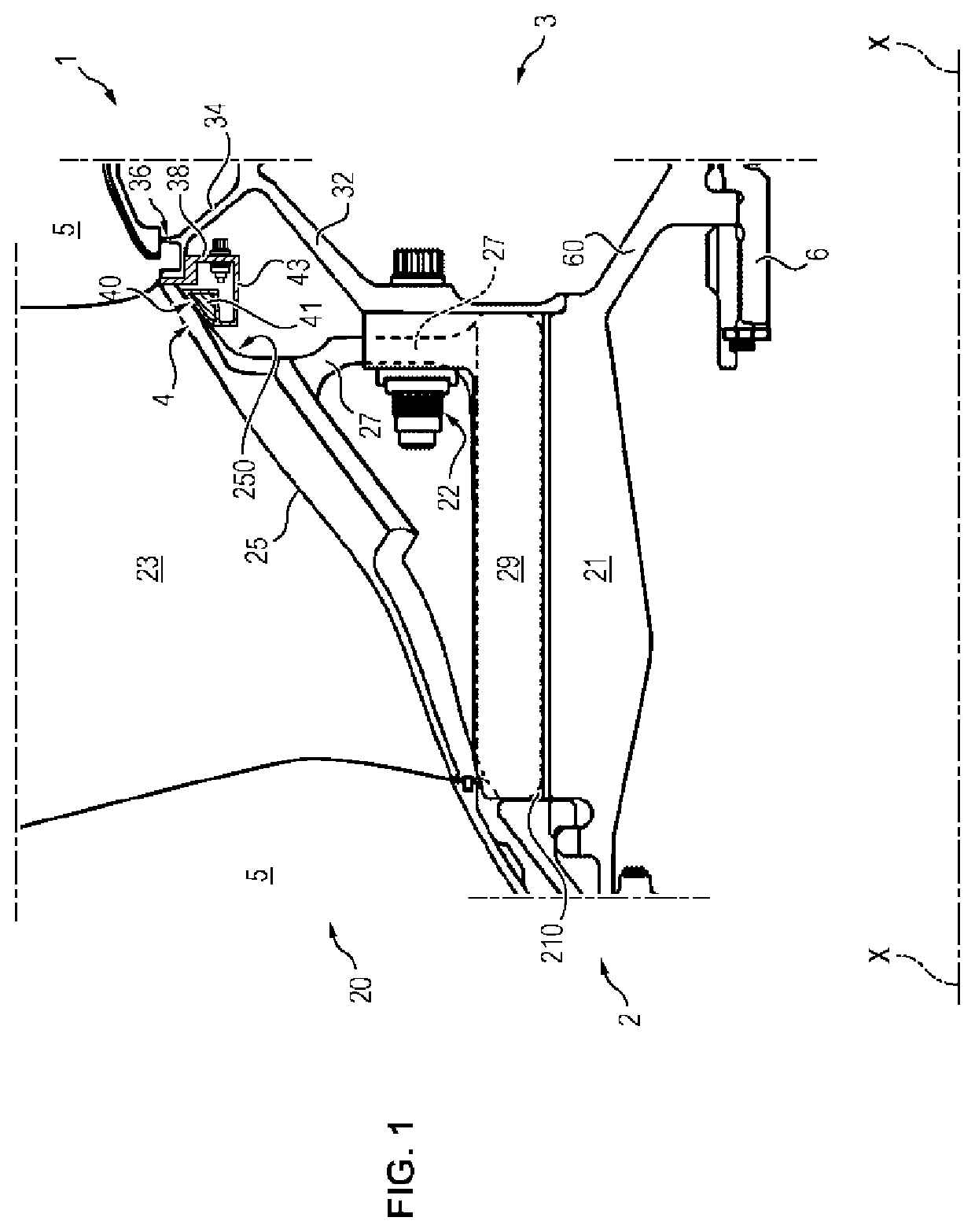
[0057]In a first embodiment illustrated in FIG. 1, the damping device 4 is accommodated below the platform 35 of a fan 2 blade 20, between the support 27 and the first low-pressure compressor 3 drum 32.

[0058]Moreover, the second module 3 comprises a ferrule 38 attached to the protruding extension 34 of the drum 32, by interference fit for example. The damping device 4 is also attached to this ferrule 38. The ferrule 38 can also be assembled to the protruding extension 34 of the drum 32, by means of alternating attachments (not shown) such as those provided by radial fingers which would belong the said ferrule 38 and which would be screwed to said extension 34.

[0059]The supporting surface 40 is upstream of the damping device 4, and is supported against the fan 2 at the internal surface 250 of the platform 25 of the fan 2 blade 20.

[0060]This assembly ensures tangential coupling with high stiffness between the fan 2 and the low-pressure compressor 3, so as to reduce the tangential vibr...

second embodiment

[0061]In a second embodiment illustrated in FIGS. 4a, 4d and 5a, the damping device 4 comprises a head 41, said head comprising a sacrificial plate 42 accommodated on the external upstream surface 40 of the damping device 4. This plate 42 is configured to guarantee the support with friction of the support surface 40 of the damping device 4 on the fan 2. Indeed, the mechanical forces during operation are such that slight tangential, axial and radial movements of the damping device 4 should be expected. These movements are in particular due to the tangential pulses to be damped, but also to the centrifugal loading of the assembly 1. It is necessary that these movements do not cause wear on the blades 20, the coatings of which are relatively fragile. In this regard, the sacrificial plate 42 comprises an anti-wear material, for example of the Teflon type, or any specific composite material known to the man skilled in the art. In addition, the sacrificial plate 42 can be treated by dry l...

third embodiment

[0066]In a third embodiment, illustrated in FIG. 4a, the damping by tangential coupling can be adjusted by controlling the mass of the damping device 4, which influences the shear inertial. This control involves modifications of the mass of the damping device 4, for example at the head 41 of the damping device 4. This mass can be modified in all or part of the damping device 4 and / or the head 41, typically by providing bores 48 for lightening, and / or by adding one or more inserts 49, metallic for example, for weighing down.

[0067]Advantageously, the combination of the second and third embodiment allows adjusting the contact forces between the damping device 4 and the fan 2. In fact, contact forces that are too high between the fan 2 blade 20 and the damping device 4 would limit the dissipation of vibrations during operation.

[0068]In another embodiment, with reference to FIGS. 4b, 4c and 4e, the ferrule 38 of the second module comprises axial extensions 381 forming a support so as to ...


PUM


Abstract

An assembly for a turbomachine including a first rotor module (2) with a first blade (20), and a second rotor module (3), connected to the first rotor module (2). The second rotor module includes a second blade with a smaller length than the first blade (20). A damping device (4) is attached to the second rotor module (3) and includes a radial external surface (40) supported with friction against the first module (2), so as to couple the modules (2, 3) for the purpose of damping their respective vibrational movements during operation.

Description

TECHNICAL FIELD[0001]The invention relates to an assembly comprising a turbomachine rotor module.[0002]The invention relates more specifically to an assembly for a turbomachine comprising two rotor modules and a damping device.PRIOR ART[0003]A turbomachine rotor module generally comprises one or more stage(s), each stage comprising a disk centered on a turbomachine longitudinal axis, corresponding to the axis of rotation of the rotor module. The rotation of the disk is generally ensured by a rotating shaft to which it is integrally connected, for example by means of a rotor module trunnion, the rotating shaft extending along the longitudinal axis of the turbomachine. Blades are mounted on the external periphery of the disk, and distributed circumferentially in a regular manner around the longitudinal axis. Each blade extends from the disk and also comprises an airfoil, a platform, a support and a root. The root is embedded in a recess of the disk configured for this purpose, the air...

Claims


Application Information

Patent Timeline
Patent Type & Authority Patents(United States)
IPC IPC(8): F01D5/10F01D5/22F04D29/32F04D29/66F01D5/26
CPCF01D5/10F01D5/22F01D5/26F04D29/324F04D29/668F05D2260/96F01D11/005F05D2230/90F05D2300/43
Inventor JOLY, PHILIPPE GERARD EDMONDCOMIN, FRANCOIS JEANJABLONSKI, LAURENTLAGARDE, ROMAIN NICOLASPERROLLAZ, JEAN-MARC CLAUDE
Owner SN DETUDE & DE CONSTR DE MOTEURS DAVIATION S N E C M A
Why Eureka
Try Eureka