Movable barrier with pressure equalization features

a technology of equalization feature and moving barrier, which is applied in the field of moving barriers, can solve the problems of not being able to mitigate dynamic changes in the ambient environment of such spaces, not being able to provide sufficient airflow from one side to the other to avoid damage to the barrier, and not being able to reduce the strength, security, and privacy provided by the barrier, so as to achieve the effect of increasing airflow and increasing airflow

Active Publication Date: 2022-09-06
THE BOEING CO
View PDF11 Cites 0 Cited by
  • Summary
  • Abstract
  • Description
  • Claims
  • Application Information

AI Technical Summary

Benefits of technology

[0002]Conventional movable barriers, such as doors, may perform well as secure partitions between spaces, but are generally not designed to mitigate dynamic changes to the ambient environments in such spaces. For example, when a large pressure differential develops across two sides of a barrier, for example in an aircraft experiencing a rapid change in cabin pressure, the barrier may not allow sufficient airflow from one side to the other to avoid damage to the barrier, structures affixed to the barrier (e.g., a bulkhead, a floor, a ceiling), and the like. While providing openings in a barrier may mitigate this issue (e.g., by allowing airflow through the barrier to allow for continued safe flying), the same openings reduce the strength, security, and privacy provided by the barrier.

Problems solved by technology

Conventional movable barriers, such as doors, may perform well as secure partitions between spaces, but are generally not designed to mitigate dynamic changes to the ambient environments in such spaces.
For example, when a large pressure differential develops across two sides of a barrier, for example in an aircraft experiencing a rapid change in cabin pressure, the barrier may not allow sufficient airflow from one side to the other to avoid damage to the barrier, structures affixed to the barrier (e.g., a bulkhead, a floor, a ceiling), and the like.
While providing openings in a barrier may mitigate this issue (e.g., by allowing airflow through the barrier to allow for continued safe flying), the same openings reduce the strength, security, and privacy provided by the barrier.

Method used


Image

  • Movable barrier with pressure equalization features
  • Movable barrier with pressure equalization features
  • Movable barrier with pressure equalization features

Examples


Embodiment Construction

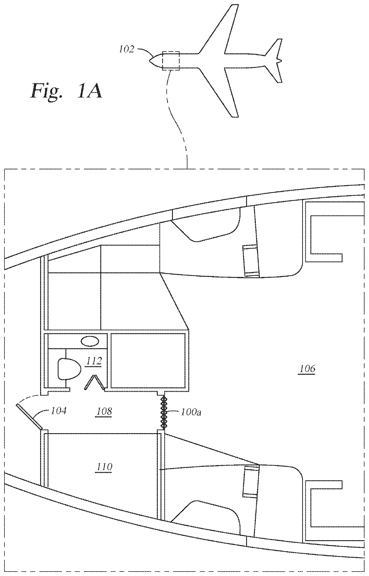
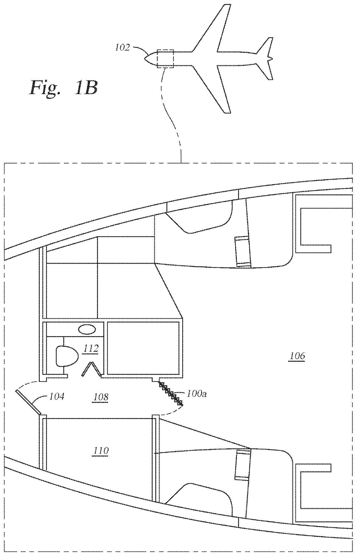
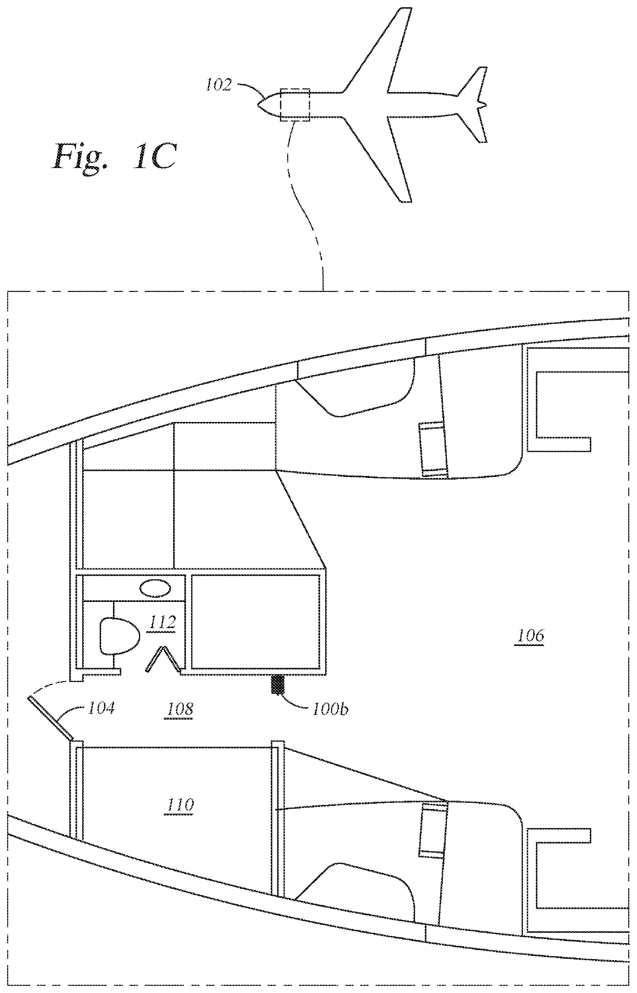
[0022]Aspects of the present disclosure provide a movable barrier that can selectively allow air passage from one side of the barrier to another while providing the privacy and security functions of a solid barrier.

[0023]In some embodiments, each side of a movable barrier includes perforations (or apertures) to allow for airflow through the barrier. Further, a deformable liner is located between each side of the movable barrier and configured to deform (e.g., tear, fold, displace, or move) when a pressure on at least one side of the deformable liner exceeds a threshold pressure difference as compared to the other side of the deformable liner, or in other words, when a differential pressure exceeding a threshold exists across the deformable liner. In this way, the deformable liner provides privacy (e.g., preventing sight through the physical perforations in the barrier) and security (e.g., preventing noxious or toxic gases through physical perforations in the barrier) under normal op...


PUM


Abstract

Certain aspects of the present disclosure provide movable barrier, including: a frame having a first side and a second side parallel to the first side; a first exterior panel connected to the first side of the frame and including: a first non-planar profile; and a first plurality of perforations; a second exterior panel connected to the second side of the frame and including: a second non-planar profile; and a second plurality of perforations; a cavity defined between the first exterior panel and the second exterior panel; and a liner disposed within the cavity and configured to: deform when an air pressure differential acting on a first side of the liner exceeds a pressure differential threshold and allow increased airflow through the movable barrier.

Description

INTRODUCTION[0001]Aspects described herein relate to movable barriers, which may generally be used for privacy and security in a variety of contexts. For example, movable barriers may be used in commercial vehicles, such as aircraft, watercraft, trains, and busses, as well as in structures, such as offices and factories, to name just a few examples.[0002]Conventional movable barriers, such as doors, may perform well as secure partitions between spaces, but are generally not designed to mitigate dynamic changes to the ambient environments in such spaces. For example, when a large pressure differential develops across two sides of a barrier, for example in an aircraft experiencing a rapid change in cabin pressure, the barrier may not allow sufficient airflow from one side to the other to avoid damage to the barrier, structures affixed to the barrier (e.g., a bulkhead, a floor, a ceiling), and the like. While providing openings in a barrier may mitigate this issue (e.g., by allowing ai...

Claims


Application Information

Patent Timeline
Patent Type & Authority Patents(United States)
IPC IPC(8): B64C1/14E06B5/12B64D45/00B64D11/00B64C1/00
CPCB64C1/1469E06B5/125B64C2001/009B64D11/0023B64D45/0026
Inventor BREIGENZER, THOMAS J.HAAS, WILLIAM C.
Owner THE BOEING CO
Why Eureka
Try Eureka