
Combined recovery system of automobile brake energy and hanger bracket vibration energy

A technology of vibration energy and automobile braking, which is applied in the direction of electric braking system, suspension, elastic suspension, etc., can solve the problems of affecting the dynamic axle load of the automobile, increasing fuel, locking, etc., and achieves the improvement of ride comfort and control Improve dynamic safety, reduce fuel consumption and exhaust emissions, and reduce the effect of dynamic changes

Active Publication Date: 2012-03-28
JIANGSU UNIV
View PDF2 Cites 18 Cited by
  • Summary
  • Abstract
  • Description
  • Claims
  • Application Information

AI Technical Summary

Problems solved by technology

During the driving process of the car, in addition to the suspension vibration and increased fuel consumption during wheel braking, the phenomenon of "brake nodding" in the braking process also increases the danger of the braking process and the discomfort of the occupants.
Because the traditional passive suspension cannot control the attitude of the vehicle body very well, the mass transfer of the vehicle body will be caused when the car brakes, which will affect the dynamic axle load of the car. When the braking force is large, it will easily cause Locking, resulting in brake flick phenomenon
[0005] Among the currently existing vehicle energy recovery devices and methods, most of them are systems and methods for recovering the braking energy or suspension vibration energy of the vehicle alone, and there is no comprehensive recovery of the vehicle suspension vibration energy and wheel braking energy. It is a device that enables the car to effectively use the braking energy to control the body posture during the braking process, which is not conducive to the effective recovery of the energy dissipated by the car

Method used


Image

  • Combined recovery system of automobile brake energy and hanger bracket vibration energy
  • Combined recovery system of automobile brake energy and hanger bracket vibration energy
  • Combined recovery system of automobile brake energy and hanger bracket vibration energy

Examples


Embodiment Construction

[0017] The present invention will be further described below in conjunction with drawings and embodiments.

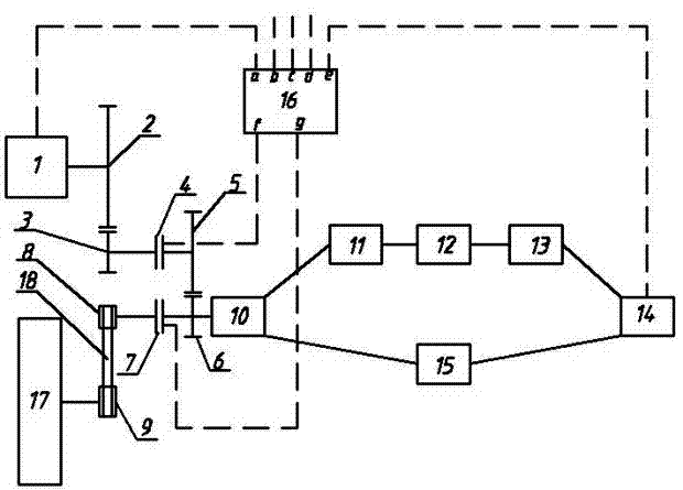
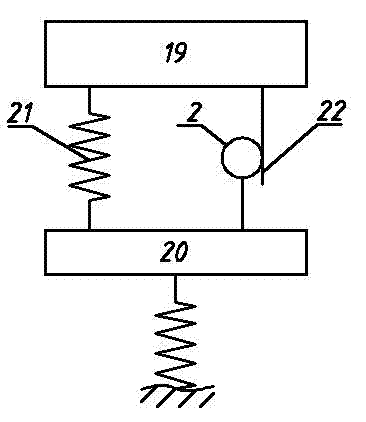
[0018] The suspension system 1 adopted by the automobile adopts a rack-and-pinion structure. The rack 22 is connected to the sprung mass 19, and the pinion gear at one end of the gear set A2 meshes with it, and the large gear at the other end meshes with the gear B3. B3 is coaxially connected with the electromagnetic clutch A4, the other end of the electromagnetic clutch is coaxially connected with the gear C5, and the gear C5 is meshed with the gear D6, and the gear D6 is coaxially connected with the motor and the electromagnetic clutch B7, and the other end of the electromagnetic clutch B It is coaxially connected with the gear E8, and the gear E8 is connected with the wheel shaft gear 9 through the chain 18, thus forming a transmission system of suspension vibration energy and wheel braking energy.

[0019] One end of the motor is connected to the rectifier 11, the o...


PUM


Abstract

The invention relates to a device capable of comprehensively recovering brake energy and hanger bracket vibration energy belonging to the technical field of energy conservation and discharge reduction of the vehicle. On the one hand, the vibration of a hanger bracket drives a motor to move so as to convert vibration energy of the hanger bracket into electric energy to store into an energy storagesystem in normal driving process of the automobile; on the other hand, the device can recover a part of brake energy of the automobile, convert the brake energy into electric energy to store into theenergy storage system through the motor, and can restrain brake dive in the brake process of the automobile through transmission between the gears so that the automobile stably brakes when the car brakes and reduces speed; and the device can convert the stored electric energy into mechanical energy to provide to the vehicle when the automobile starts up or accelerates so as to save energy and ensure stable operation of the automobile.

Description

technical field [0001] The invention relates to a combined recovery system of automobile braking energy and suspension vibration energy, which belongs to the technical field of automobile energy saving. Background technique [0002] When the car is running on the road, due to the excitation of the uneven road surface and various complex road conditions, part of the energy of the car is converted into heat energy and dissipated through the shock absorber during the vibration of the suspension; In the process of driving, a large amount of kinetic energy is also converted into heat energy through friction and dissipated, which not only wastes energy, but also accelerates the wear and tear of the brake system of the car. If these two parts of energy can be recovered, the fuel consumption can be reduced to a great extent, and the damage to the environment caused by the increasing number of cars can also be reduced. Therefore, the recovery of suspension vibration energy and wheel ...

Claims


Application Information

Patent Timeline
Patent Type & Authority Applications(China)
IPC IPC(8): B60L7/18B60G17/016
CPCY02T10/7241Y02T10/72
Inventor 汪若尘施德华陈龙江浩斌
Owner JIANGSU UNIV
Learn More