
Dynamic ventilation system for socks

a ventilation system and ventilation system technology, applied in the field of socks, can solve the problems of affecting the comfort of users, and affecting the comfort of users, and achieve the effect of good compression and excellent breathability

Active Publication Date: 2022-09-20
TRERE INNOVATION SRL
View PDF62 Cites 1 Cited by
  • Summary
  • Abstract
  • Description
  • Claims
  • Application Information

AI Technical Summary

Benefits of technology

The present invention aims to solve problems in the prior art by providing a dynamic ventilation system for socks that offer optimal comfort, breathability, compression, and protection of the foot and leg. The invention has structural features that respond to movements, effort, stress, and pressures to which the skin, muscles, and bones are subjected during movements. Additionally, the invention offers zones of control and maintenance of contact with the footwear while creating a comfortable and soft zone in contact with the skin. The invention is easy to make and very functional.

Problems solved by technology

These alternations of temperature create a sensation of heat and cold that is decidedly unpleasant for the user, who does not have a positive and comfortable sensation on the skin but above all on the foot, where sweating is more marked.
In particular, if the temperature increases too much, damage can be caused to the cellular matrix of the muscles because the flow of muscle fibres at certain temperatures and under stress is not optimum.
From studies made, it has been found that the lack of dissipation and / or irregular dissipation causes a forced and further temperature increase that leads to an acceleration of the previously mentioned effects that, over time, cause vascular wear.
Further, excessive heat reduces the viscosity of the surfactant liquids present among the muscles with the consequence that performance is reduced, increasing the risk of cell and muscle damage.
This zone is only a psychological help but is not real and effective.

Method used


Image

  • Dynamic ventilation system for socks
  • Dynamic ventilation system for socks
  • Dynamic ventilation system for socks

Examples


Embodiment Construction

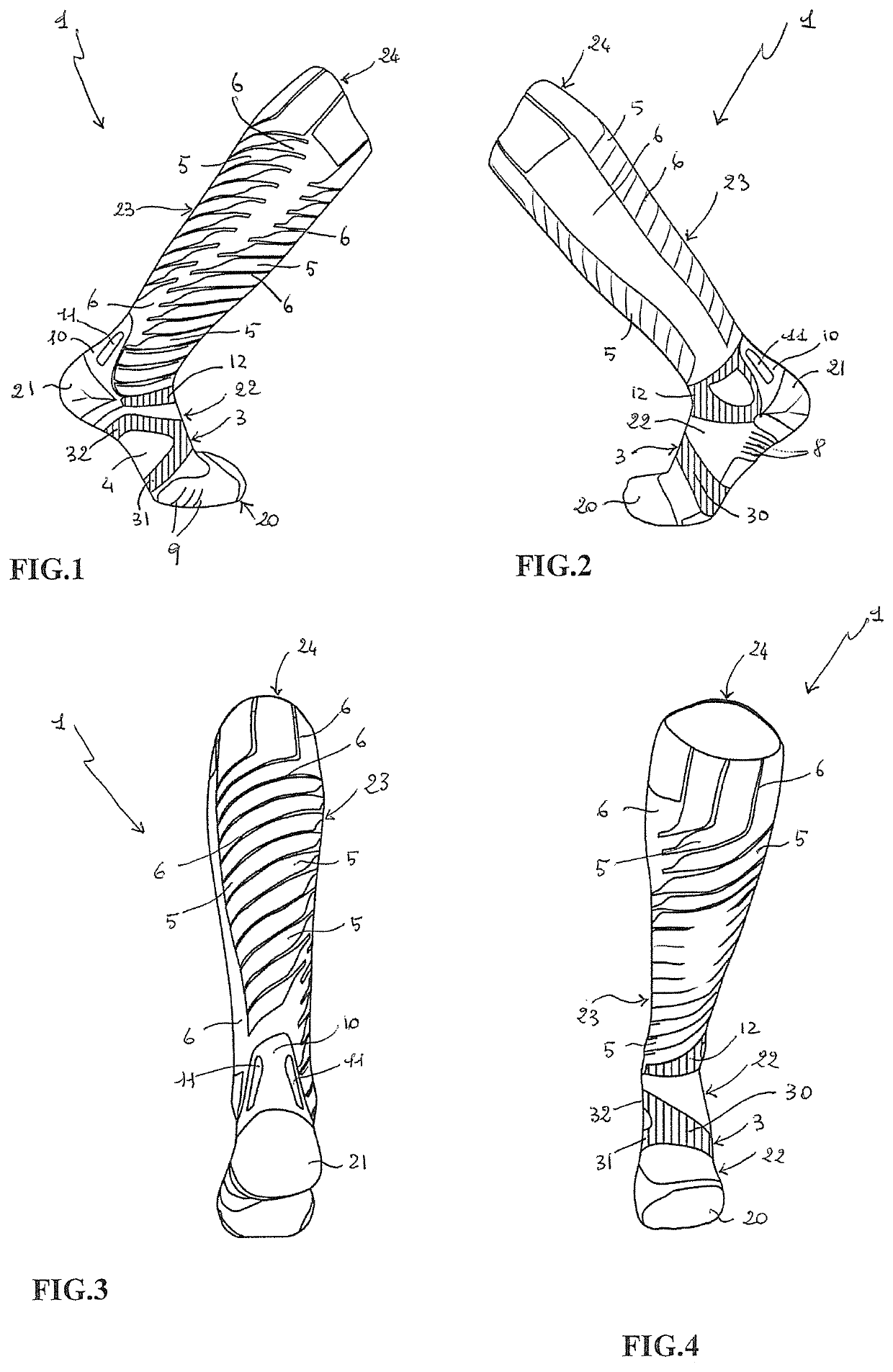
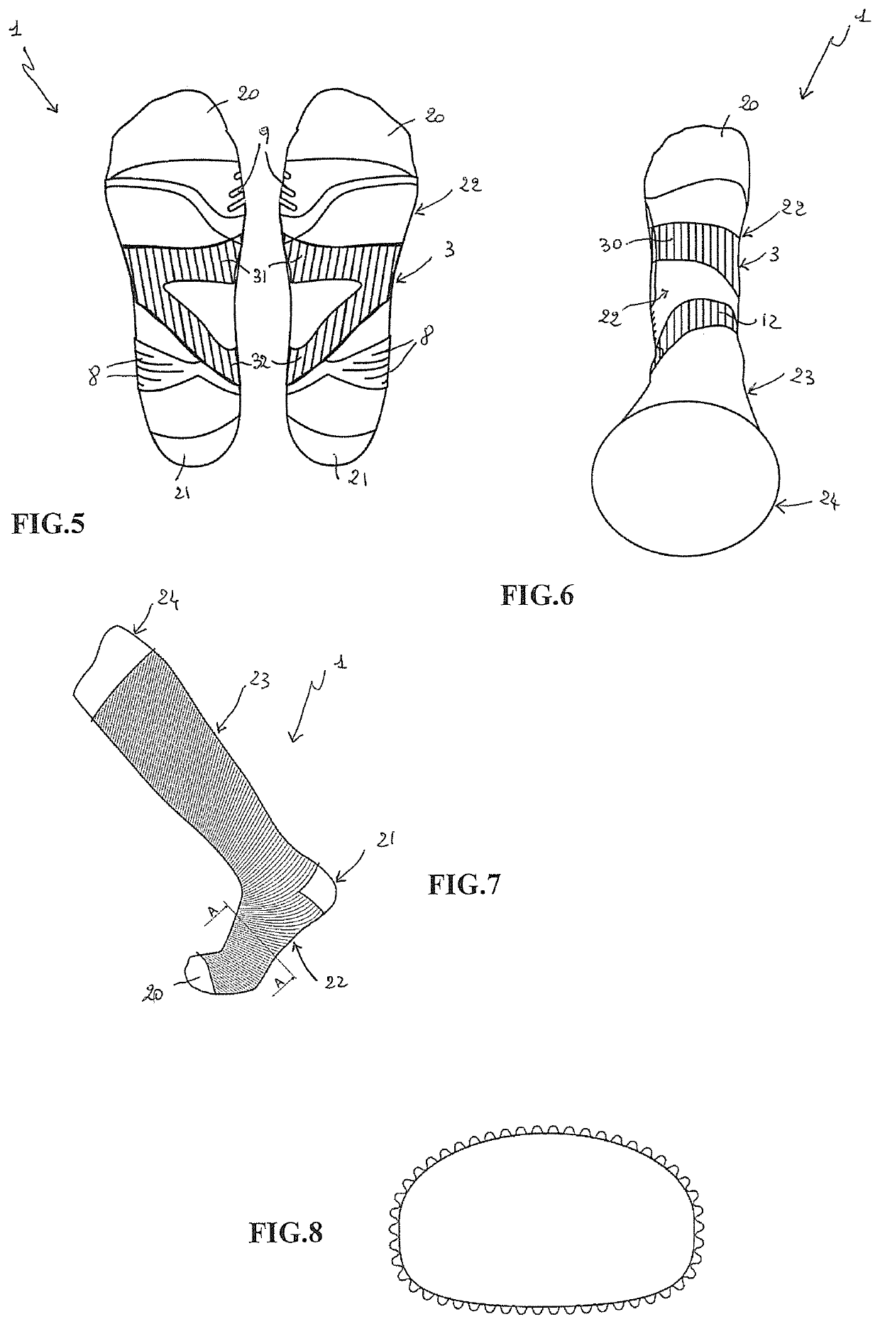
[0036]As shown in the figures, the sock 1 in question presents itself and is configured as a classic sock with a toe 20, a traditional heel 21, a part 22 that envelops the foot, a part 23 that envelops the ankle and the leg and an elasticated edge 24 provided for adhering to the leg of the user so as to ensure that it does not slide along the leg.

[0037]The sock made according to the present invention provides sectors that have different structures and differentiated processing that enable the sock to acquire well defined functional features depending on the zone, as will be better illustrated proceeding with the description.

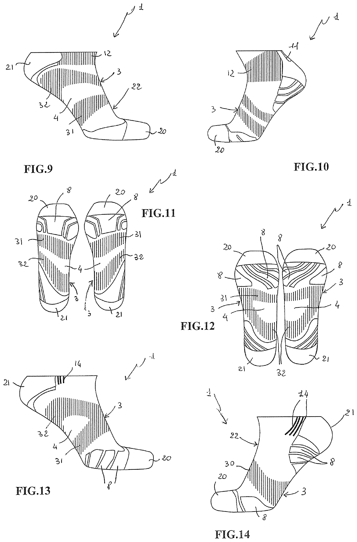
[0038]According to the present invention, the dynamic ventilation system for socks comprises a strip structure 3 that has the task of containing the plantar arch so as to create inside a sector 4 that has a mesh with open and sparse processing, so as to let air pass through.

[0039]In particular, the sector 4 is an integrated aerating zone to enable this part of th...


PUM


Abstract

A dynamic ventilation system for socks including an ergonomic and asymmetric strip structure (3) which contains the plantar arch so as to create internally an integrated aerating sector (4). Further, the system has a first structure with a transparent zone in which an air circulating system is created that is provided for regulating the temperature of the foot and leg, containing a certain quantity of air between skin and sock so as to create an “air chamber” with an effect of insulating from the external environment and a second structure having a plurality of contact sectors (5) that have greater support on the skin that are interrupted by free portions (6) for the passage of air. The system further includes a pair of ribs (11) that create a passage / tunnel for circulating air in addition to increasing Achilles tendon protection in which each rib is a cushion that fills with air.

Description

TECHNICAL FIELD[0001]The present invention relates to a dynamic ventilation system for socks that is particularly suitable for creating differentiated zones having a specific and localized function depending on the position and being able to obtain effective breathability and precise and even heat regulation of the foot and leg, at the same time offering support, cushioning protection and micromassage that helps blood circulation and muscles during sporting activities.BACKGROUND ART[0002]Today, the need to have garments and in particular socks with increasingly specialist and precise performance is driving research into developing weaving and processing that are increasingly high-performance and aim at being able to respond to specific comfort, heat regulation, resistance, containment, protection, support and sustaining, etc. requirements.[0003]One need that the market has made felt is that of being able to have available for the different sports disciplines socks that are increasin...

Claims


Application Information

Patent Timeline
Patent Type & Authority Patents(United States)
IPC IPC(8): A41B11/02
CPCA41B11/02A41B2400/20A41B2400/60
Inventor GIORGINI, FABIO
Owner TRERE INNOVATION SRL
Learn More