Eureka AIR delivers breakthrough ideas for toughest innovation challenges, trusted by R&D personnel around the world.

Condensate lifting device comprising a movable condensate receiving tank, or mounted on a support movable in translation and/or rotation

Active Publication Date: 2022-09-20
SAUERMANN IND
View PDF17 Cites 0 Cited by
  • Summary
  • Abstract
  • Description
  • Claims
  • Application Information

AI Technical Summary

Benefits of technology

The present invention is a condensate lifting device that solves problems in the prior art by providing a movable tank and pump for lifting condensates. The pump is mounted on a support that can hold and guide the tank, allowing it to take at least two positions. The device also includes means for detecting the level of condensates in the tank and indicating the need for draining or maintenance. The device can be housed in a casing and is designed to work with a left or right side of an HVAR system. The technical effects of the invention include improved efficiency, better control, and reduced downtime for maintenance.

Problems solved by technology

In other words, the components of the condensate lifting device are supplied and then installed separately, or independently of each other, which implies the use of a relatively large number of (hydraulic and electrical) connection elements, possible installation difficulties, and risks of malfunction, loss of time and money, .
In addition, it can be difficult for the technician to install some of these components, which must occupy a specific position within the air conditioning system, in areas that are sometimes difficult to access.
The alarm cable sometimes poses installation difficulties for technicians: indeed, it may be difficult to link it to an air conditioner that has not been explicitly designed to cooperate with the considered lifting device.
Improper installation of the alarm system is however detrimental to the correct operation of the condensate lifting device, since there is then a risk that an abnormally high condensate level in the tank is detected, but does not cause stopping the air conditioning, leading to condensate overflowing out of the tank and possibly damaging the lifting device and / or its surroundings.
The maintenance of condensate removal devices can also be problematic, due to the poor accessibility of the various components.
However, the condensate lifting pump and the condensate receiving tank can generally be reached by the maintenance technician only by first dismounting one or more parts of the air conditioner or its surroundings, which involves a consequent loss of time and efficiency.
Finally, over the long term, the reliability of the condensate level detection devices currently used in lifting systems is not always guaranteed, as their positioning can indeed be out of order.
The relative heights of the condensates detected in the tank can thus be falsified and consequently lead to a risk of failure of the condensate lifting device, for example a too late triggering of the pump causing condensate leaks.

Method used


Image

  • Condensate lifting device comprising a movable condensate receiving tank, or mounted on a support movable in translation and/or rotation
  • Condensate lifting device comprising a movable condensate receiving tank, or mounted on a support movable in translation and/or rotation
  • Condensate lifting device comprising a movable condensate receiving tank, or mounted on a support movable in translation and/or rotation

Examples


Embodiment Construction

5.0 General Principle

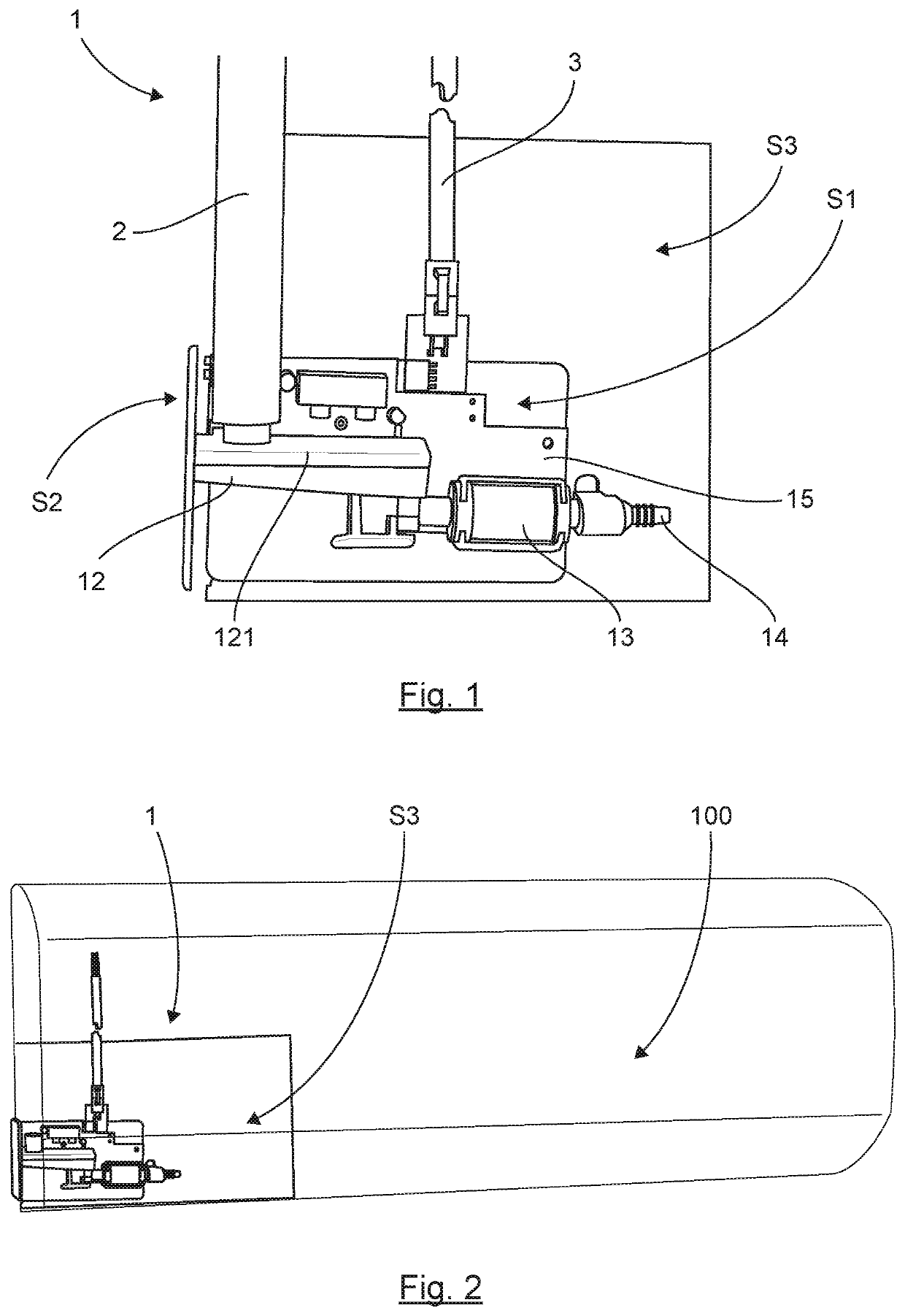
[0065]The invention provides a new approach to the architecture of a condensate lifting device, allowing to simplify the manufacturing, installation and maintenance operations of the device.

[0066]5.0.1 Preventive Maintenance: Access to the Tank

[0067]The condensate lifting device comprises in particular a condensate receiving tank which must be subjected to a regular control aiming at preventing any stagnation of the condensates which could cause the formation of biofilm, aqueous and gelatinous matrix secreted by bacteria in the liquid, and which promotes bacterial proliferation.

[0068]The condensate receiving tank must therefore be easily accessible so that it can be drained and cleaned regularly, in order to eliminate the condensate which would not have been evacuated by the condensate lifting pump.

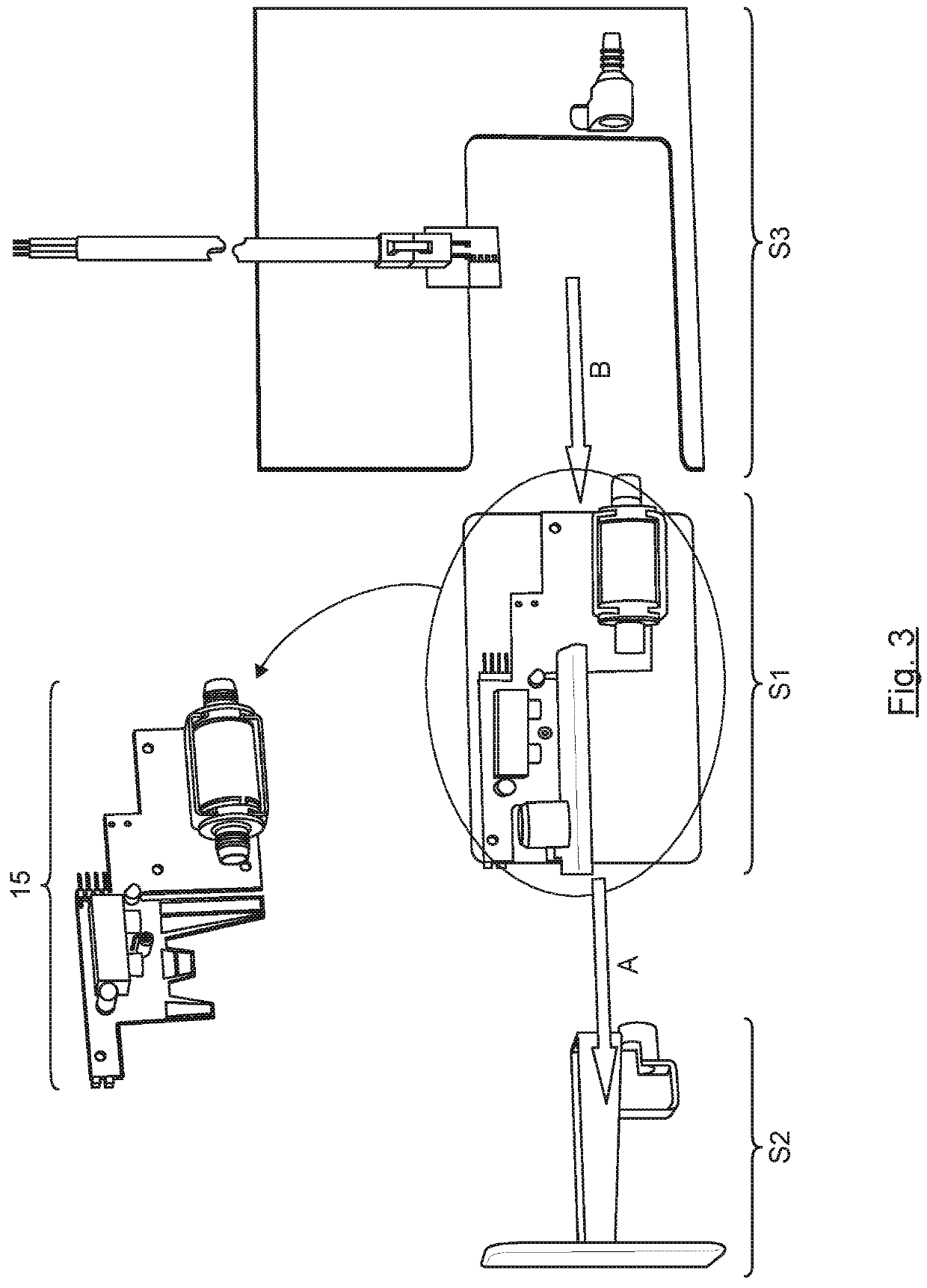
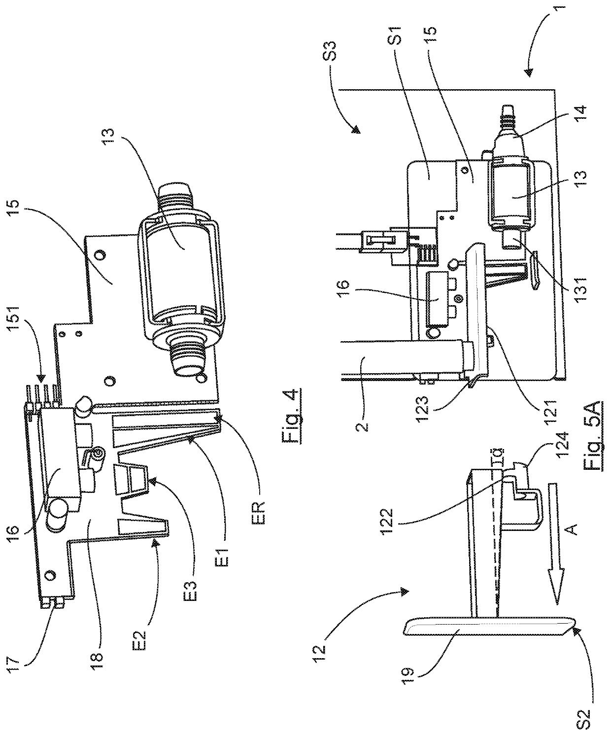
[0069]For this purpose, the condensate receiving tank is movable in translation and / or in rotation relative to a pump support, or first support, carrying a pump inten...


PUM


Abstract

A condensate lifting device, including: a condensate receiving tank and a pump for lifting the condensates received in the tank. The pump is mounted on a first support for holding and / or guiding the tank or a second support carrying the tank, so that the tank or the second support is movable, in translation and / or in rotation, relative to the first support, so as to be able to take at least two positions: a working position, wherein the tank is connected to the pump; and a drainage position, wherein the tank is disconnected from the pump and displaced relative to the first support, so as to allow an operation of cleaning and / or draining the condensates.

Description

CROSS-REFERENCE TO RELATED APPLICATIONS[0001]This Application is a Section 371 National Stage Application of International Application No. PCT / EP2019 / 070230, filed Jul. 26, 2019, which is incorporated by reference in its entirety and published as WO 2020 / 025491 A1 on Feb. 6, 2020, not in English.FIELD[0002]The field of the invention is that of condensate lifting devices, intended to be implemented in systems producing condensates, in particular air conditioning systems, refrigerating systems, ventilation systems or heating systems.PRIOR ART[0003]In what follows, the focus is more particularly on describing the problem existing in the field of air conditioning systems, with which the inventors of the present patent application were confronted.[0004]However, the invention is not limited to this particular field of application but applies to all systems producing condensates, in particular systems of the “HVAR” (for “Heating, Ventilation, Air-conditioning and / or Refrigeration”) type.[0...

Claims


Application Information

Patent Timeline
IPC IPC(8): F24F13/00F24F13/22
CPCF24F13/222F24F2013/227F24F11/89
Inventor DE GEA, OLIVIERSARDET, FRANÇOISGUILLARD, LAURENT
Owner SAUERMANN IND
Why Eureka
Eureka Blog
Learn More