Heat exchanger and fin of the same

a heat exchanger and fin technology, applied in the field of fins of heat exchangers, can solve the problems of reducing the heat exchanger heat exchange efficiency and the inability to quickly drain condensed water, and achieve the effect of improving heat exchange efficiency and reducing power consumption of heat exchangers

Inactive Publication Date: 2007-07-05
LG ELECTRONICS INC
View PDF6 Cites 51 Cited by
  • Summary
  • Abstract
  • Description
  • Claims
  • Application Information

AI Technical Summary

Benefits of technology

[0021] An advantage of the present invention is the promp draining away of condensed water generated on a surface of a fin to prevent the condensed water from flowing into an indoor area.
[0022] Another advantage of the present invention is that heat exchanging efficiency is improved through prompt drainage o...

Problems solved by technology

However, a plurality of slits in the structure of the heat exchanger fin according to a related art prevents condensed water from flowing, so that the condensed water cannot drain qui...

Method used


Image

  • Heat exchanger and fin of the same
  • Heat exchanger and fin of the same
  • Heat exchanger and fin of the same

Examples


Embodiment Construction

[0029] Reference will now be made in detail to the preferred embodiments of the present invention, examples of which are illustrated in the accompanying drawings. Wherever possible, the same reference numbers will be used throughout the drawings to refer to the same or like parts.

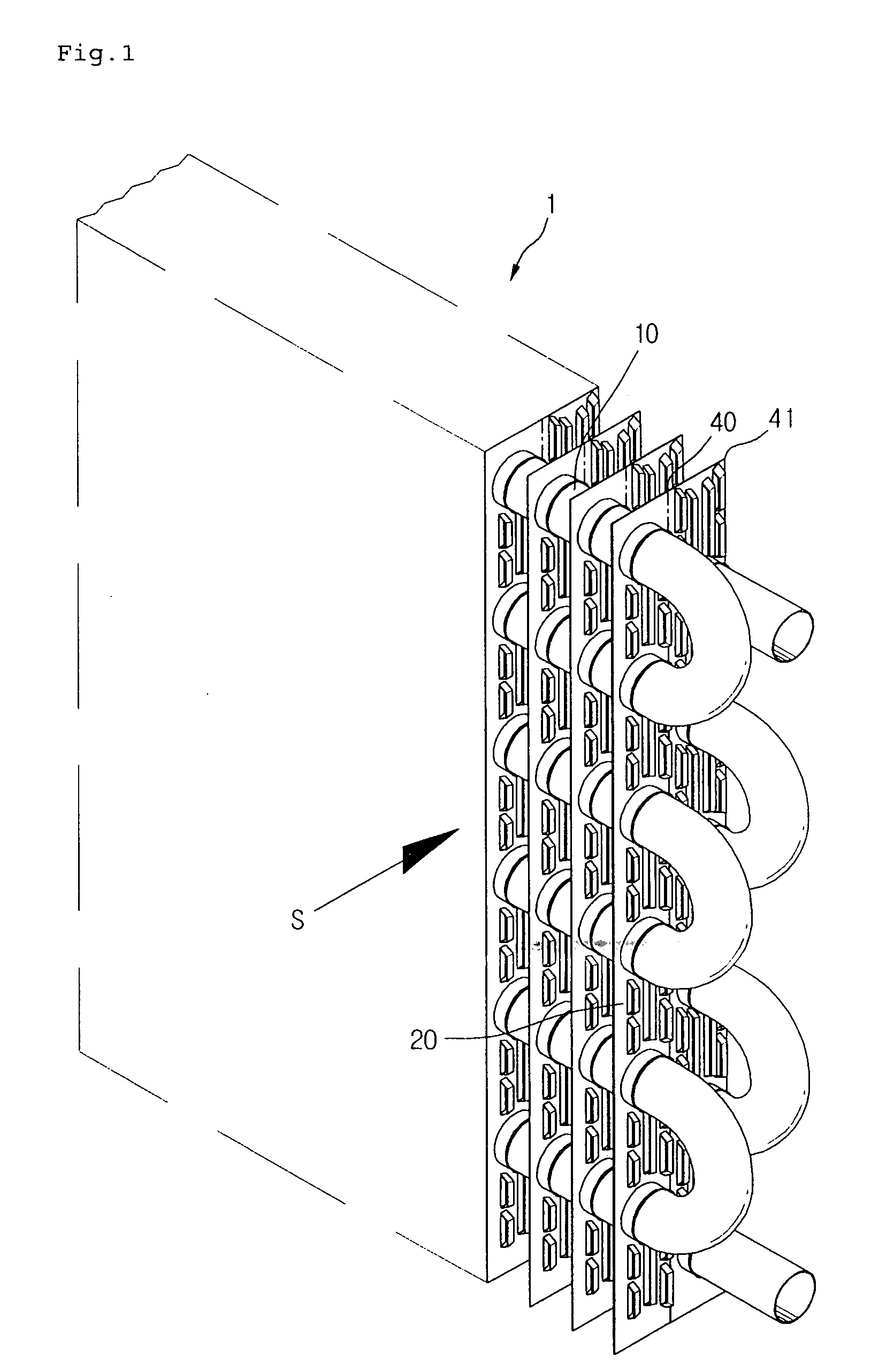
[0030]FIG. 1 is a perspective view according to the present invention.

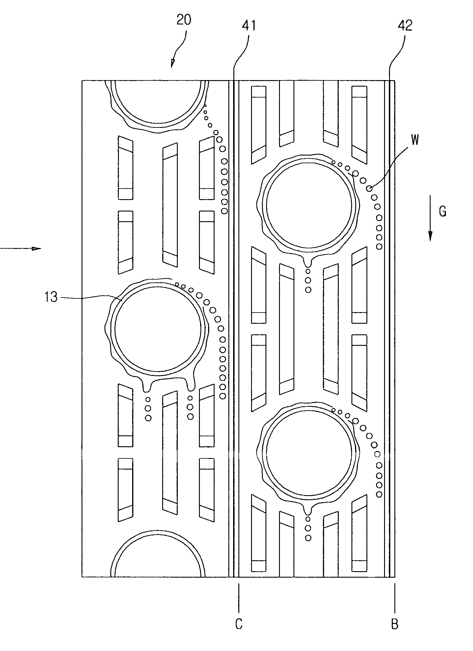
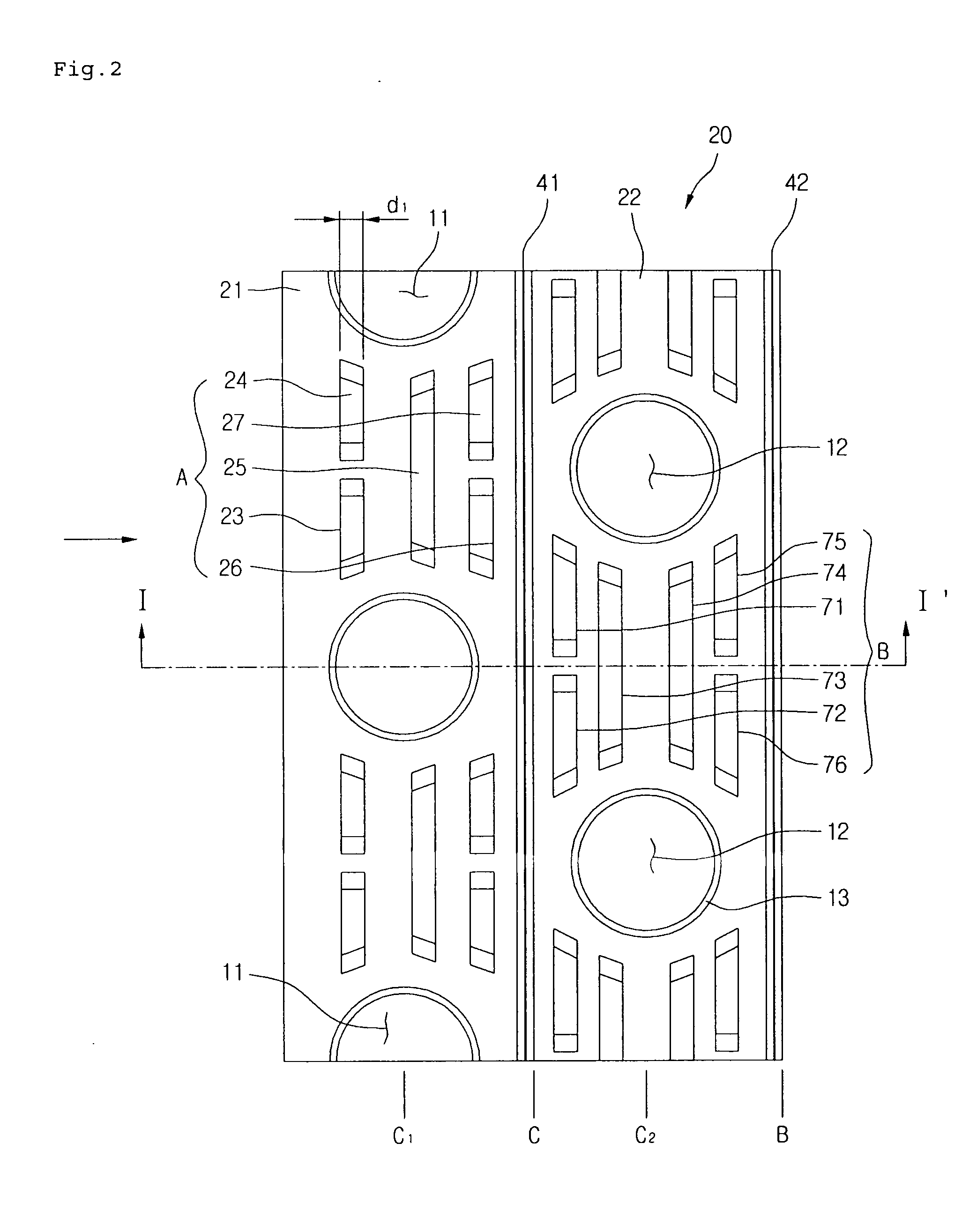
[0031] Referring to FIG. 1, a heat exchange 1 includes a tube 10 arranged with at least a front and a rear row, a plurality of fins 20 installed through the fin 10.

[0032] In detail, the tube 10, through which refrigerant flows, has a predetermined length and is bent multiple times. Also, the fins are spaced from each other at a predetermined distance and are perpendicular to the tube.

[0033] Here, a front and a rear row tube are arranged in a zigzag pattern to promote heat exchange at each tube.

[0034] The fin 20 is formed of a thin plate to expand a heat transfer area that contacts air and improves the efficiency of heat transfer.

[00...


PUM


Abstract

A heat exchanger and a fin of the same are provided. The heat exchanger includes a tube, a plurality of fins, a slit section, and a condensed water guide. The tube is arranged in at least a front row and a rear row with respect to a direction of airflow. The plurality of fins is installed with the tube passing therethrough. The slit section is formed on the fins and includes a plurality of slits. The condensed water guide is formed between at least the front row and the rear row, for guiding a draining of condensed water that is generated on a surface of the tube. A fin of the heat exchanger includes a plurality of tube insert holes, a slit section, and a condensed water guide. A refrigerant tube is inserted in the plurality of tube insert holes. The slit section includes a plurality of slits formed around the tube insert holes. The condensed water guide is formed at a rear side of one of the slits, and guides a draining of condensed water generated in a heat exchange process between refrigerant and air.

Description

BACKGROUND OF THE INVENTION [0001] 1. Field of the Invention [0002] The present invention relates to a fin of a heat exchanger, and more particularly, to a heat exchanger and a fin of the same for promptly draining condensed water to increase a heat exchanging efficiency of the heat exchanger and prevent a carry-over phenomenon where condensed water overflows into an indoor area. [0003] 2. Description of the Related Art [0004] In general, a heat exchanger is an apparatus for exchanging heat between refrigerant and air, and has various applications including air conditioners. Heat exchangers are mainly embodied in the form of finned tubes. [0005] In a heat exchanger according to a related art, a plurality of fins is vertically stacked and spaced from each other by a predetermined distance. A tube is installed through the fins and bent multiple times, through which refrigerant circulates. The fin is installed perpendicular to the tube to expand an area of heat exchange between the ref...

Claims


Application Information

Patent Timeline
IPC IPC(8): F28F1/32
CPCF28F17/005F28F1/325
Inventor LEE, HAN CHOONJANG, DONG YEONLEE, SANG YEULKIM, JU HYOKSA, YONG CHEOL
Owner LG ELECTRONICS INC
Why Eureka
Try Eureka