Touchpad device

a touchpad and device technology, applied in the field of input devices, can solve the problems of inability to accurately press the portion of the touchpad away from the pivot side, inconvenience in operation, influence on operation feelings, etc., and achieve the effect of reducing the operation noise of the touchpad device and improving the operation feeling for users

Active Publication Date: 2022-09-20
CHICONY ELECTRONICS
View PDF17 Cites 2 Cited by
  • Summary
  • Abstract
  • Description
  • Claims
  • Application Information

AI Technical Summary

Benefits of technology

[0009]Based on the above, in the touchpad device according to one or some embodiments of the instant disclosure, the first linkage member and the second linkage member are disposed between the substrate and the circuit board. Therefore, when any portion of the touchpad device (e.g., any corner or any edge of the touchpad device) is pressed, the pressing force would always allow the circuit board and the resilient member to come close to, to abut against, and to press each other, thereby generating pressing feelings of the touchpad device for the user. Moreover, the first outer side of the first linkage member is sandwiched between the first limiting member of the annular plate and the circuit board. Therefore, upon operation, the first linkage member can be prevented from having deflection and wobbling, thereby reducing the operation noise of the touchpad device as well as improving the operation feelings for the user.

Problems solved by technology

However, when the user operates the touch panel, he or she would not always accurately press the portion of the touch panel away from the pivot side.
Hence, when the user presses the pivot side of the touch panel or presses a region or a corner adjacent to the pivot side, the pressing force of the user cannot allow the touch panel to be moved downwardly smoothly, thus failing to generate corresponding signal(s), and thereby causing inconvenience in operation, influence in operation feelings, and other issues.

Method used


Image

  • Touchpad device
  • Touchpad device
  • Touchpad device

Examples


Embodiment Construction

[0025]It should be noted that, in the descriptions for the embodiments, the ordinal numbers, e.g., “first”, “second”, “third”, “fourth”, etc., are used to describe different elements, and these elements are not limited due to the use of these ordinal numbers. Moreover, for sake of convenience and clarity, the thicknesses or the dimensions of the elements in the drawings are presented exaggeratedly, omittedly, or generally, and the person having ordinary skills in the art still can realize and read. The sizes shown in all the drawings in reference with the specification, are not intended to limit the present disclosure, but merely facilitate the understanding and reading for those skilled in the art. Modifications and variations in different scale or sizes can be made without departing from the spirit of the present disclosure. In all the drawings, the same reference numbers are used to indicate the same or similar elements.

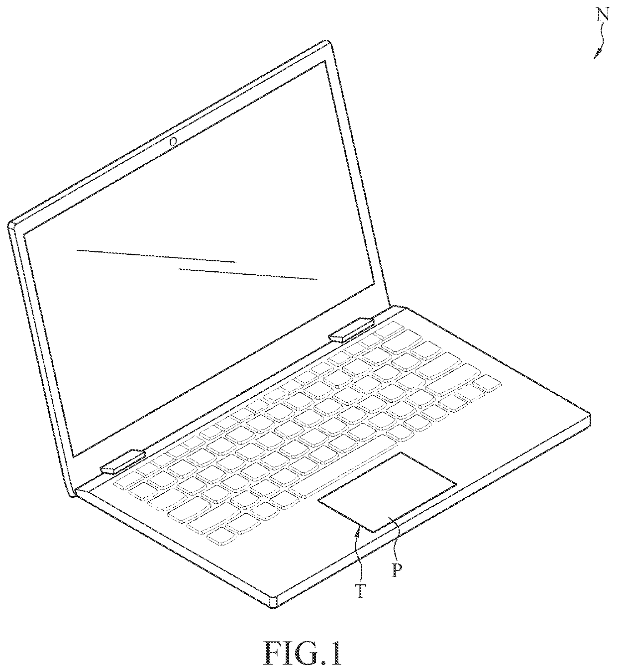
[0026]FIG. 1 illustrates a schematic application view of a t...


PUM


Abstract

A touchpad device includes a substrate, a circuit board, a resilient member, an annular plate, a first linkage member, and a second linkage member. The circuit board is disposed above a top surface of the substrate. The resilient member, the first linkage member, and the second linkage member are disposed between the substrate and the circuit board. The annular plate is fixed around a bottom surface of the circuit board and includes an inner periphery. The inner periphery includes a first side, a second side, a third side, and a fourth side connected to each other. The first linkage member includes a first swing plate, and the first swing plate includes a first outer side and a first inner side. The first inner side is swingably connected to the substrate, and the first outer side is sandwiched between the first limiting member and the circuit board.

Description

CROSS-REFERENCE TO RELATED APPLICATION[0001]This non-provisional application claims priority under 35 U.S.C. § 119(a) to Patent Application No. 110112822 filed in Taiwan, R.O.C. on Apr. 8, 2021, the entire contents of which are hereby incorporated by reference.BACKGROUND[0002]Technical Field[0003]The instant disclosure relates to an input device, in particular, to a touchpad device.[0004]Related Art[0005]Touchpads are common input devices widely applied in computers. The touchpad is provided for sensing the movement or pressing of a user's finger(s) to control the cursor to perform an action (e.g., to move, to click, or the like).SUMMARY[0006]A touchpad known to the inventor has a touch panel and a substrate. The touch panel has a pivot side, and the touch panel is pivotally fixed on the substrate through the pivot side. When a portion of the touch panel away from the pivot side is pressed, the touch panel swings downwardly with respect to the substrate by taking the pivot side as t...

Claims


Application Information

Patent Timeline
Patent Type & Authority Patents(United States)
IPC IPC(8): G06F3/041G06F3/0354G06F1/16
CPCG06F3/03547G06F1/169G06F1/1616G06F1/1658
Inventor LI, PO-HSIN
Owner CHICONY ELECTRONICS
Why Eureka
Try Eureka