Dual-pattern optical 3D dimensioning

a 3d dimensioning and optical technology, applied in the field of optical 3d dimensioning, can solve the problems of affecting the triangular geometry, introducing the loss of accuracy, and limited ultimate accuracy,

Active Publication Date: 2022-09-20
HONEYWELL INT INC
View PDF27 Cites 2 Cited by
  • Summary
  • Abstract
  • Description
  • Claims
  • Application Information

AI Technical Summary

Problems solved by technology

In some examples, optical 3D dimensioning with structural light triangulation imaging (parallax) suffers accuracy loss introduced by variations in relative positions and orientations of a projector, a camera, and a projector-camera pair.
The dimensioning accuracy problem can be, in some examples partially solved with calibration, but the ultimate accuracy is still limited due to the non-calibratable part of the variations, such as shock and vibration.
In addition, temperature change of the system due to the ambient temperature change or self-generated heat may affect the triangular geometry.
Temperature gradient change occurring due to the nonuniform heat-generating source and non-homogeneous heat dissipation may also introduce complex deformations to the triangular system geometry and individual components.
More specifically, changes in camera focusing and distortion may directly contribute to the 3D dimensioning error.
Additionally, such changes are difficult to control or correct with calibration.
Such a combination introduces challenges in compensating for the changes in pattern image positions on the image sensor introduced by the thermal expansion.
Applicant has identified a number of deficiencies and problems associated with conventional housing and apparatuses for dimensioning devices.

Method used


Image

  • Dual-pattern optical 3D dimensioning
  • Dual-pattern optical 3D dimensioning
  • Dual-pattern optical 3D dimensioning

Examples


Embodiment Construction

[0051]The present disclosure now will be described more fully hereinafter with reference to the accompanying drawings in which some, but not all, embodiments of the disclosure are shown. Indeed, embodiments of the disclosure may be embodied in many different forms and should not be construed as limited to the embodiments set forth herein; rather, these embodiments are provided so that this disclosure will satisfy applicable legal requirements. Like numbers refer to like elements throughout. As used herein, positional terms may be used in examples to describe the relative position of certain components or portions of components. Furthermore, as would be appreciated to one of ordinary skill in the art in light of the present disclosure, the terms “substantially” and “approximately” indicate that the referenced element or associated description is accurate to within applicable engineering tolerances.

Overview

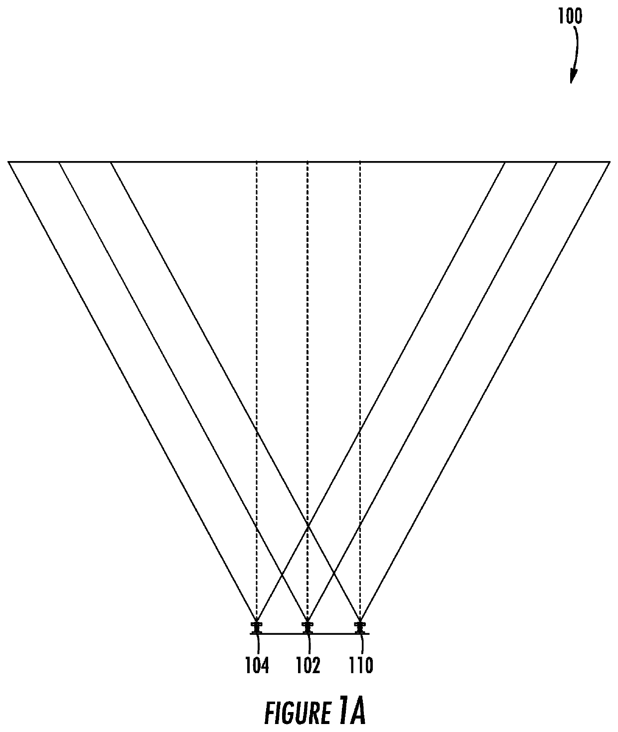
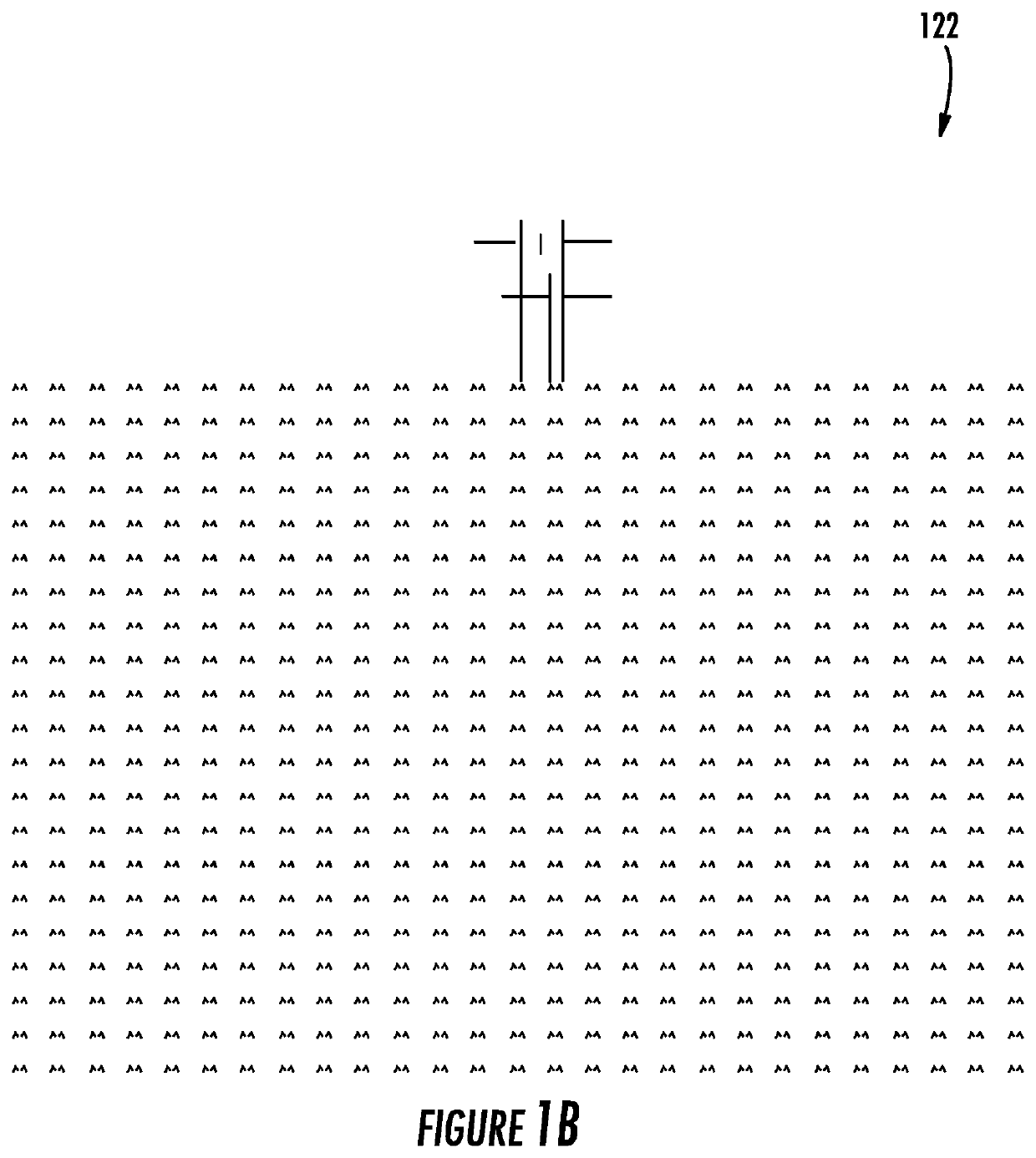
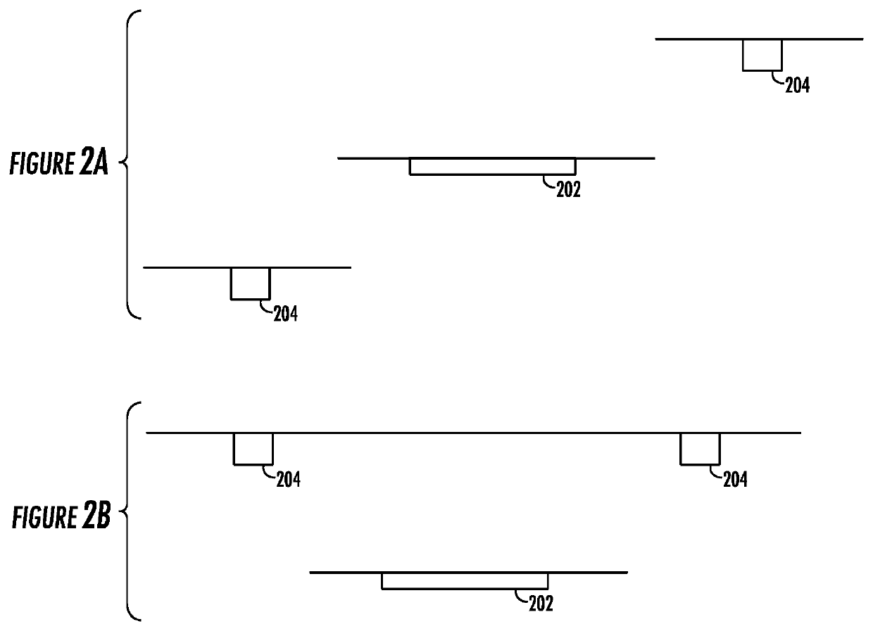
[0052]Projectors and corresponding detection systems may utilize structured lig...


PUM


Abstract

An optical dimensioning system includes one or more light emitting assemblies configured to project one or more predetermined patterns on an object; an imaging assembly configured to sense light scattered and / or reflected off the object, and to capture an image of the object while the patterns are projected; and a processing assembly configured to analyze the image of the object to determine one or more dimension parameters of the object. The light emitting assembly may include a single piece optical component configured for producing a first pattern and second pattern. The patterns may be distinguishable based on directional filtering, feature detection, feature shift detection, or the like. A method for optical dimensioning includes illuminating an object with at least two detectable patterns; and calculating dimensions of the object by analyzing pattern separate of the elements comprising the projected patterns. One or more pattern generators may produce the patterns.

Description

FIELD OF THE INVENTION[0001]The present disclosure relates generally to optical dimensioning, and more particularly to dual-pattern optical 3D dimensioning.BACKGROUND[0002]In some examples, optical 3D dimensioning with structural light triangulation imaging (parallax) suffers accuracy loss introduced by variations in relative positions and orientations of a projector, a camera, and a projector-camera pair. These variations can result from the thermal, structural, or other changes, such as component aging. The dimensioning accuracy problem can be, in some examples partially solved with calibration, but the ultimate accuracy is still limited due to the non-calibratable part of the variations, such as shock and vibration. In addition, temperature change of the system due to the ambient temperature change or self-generated heat may affect the triangular geometry. Temperature gradient change occurring due to the nonuniform heat-generating source and non-homogeneous heat dissipation may a...

Claims


Application Information

Patent Timeline
Patent Type & Authority Patents(United States)
IPC IPC(8): G06V10/24G06T7/521G06T7/246G01B11/25G06V10/145G06V10/147
CPCG06V10/245G01B11/2513G06T7/246G06T7/521G06V10/145G06V10/147G06V2201/12G01B11/2531G06T7/586
Inventor XIAN, TAOFENG, CHENPOLONIEWICZ, PAULBRACKEN, SCOTT
Owner HONEYWELL INT INC
Why Eureka
Try Eureka