

Communication apparatus and communication method
a communication apparatus and communication method technology, applied in the direction of digital transmission, wireless communication, transmission path sub-channel allocation, etc., can solve the problems of difficult to perform flexible communication control, difficult to obtain communication opportunities, and difficult to communicate by autonomous decentralized communication. achieve the effect of flexible allowing a communication terminal to transition
- Summary
- Abstract
- Description
- Claims
- Application Information
AI Technical Summary
Benefits of technology
Problems solved by technology
Method used
Image

Examples
first embodiment
4. Modification of First Embodiment
[0150](4-1. First Modification)
[0151]The above description is an example in which transition information regarding transition from the centralized communication mode to another mode is arranged in the trigger frame. Hereinafter, as a modification of the first embodiment, an example in which the transition information is arranged in another frame will be described.
[0152]FIG. 12 is a diagram illustrating operation of the AP 100 and the STA 200 in a case where the transition information regarding the duration of the centralized communication mode is arranged in the M-BA frame. Note that the M-BA frame is transmitted to the STA 200 for which transmission of data has been permitted by the trigger frame. However, the STA 200 for which transmission of data has not been permitted may obtain the transition information with reference to the region of the M-BA frame that can be referred to by all of the STAs 200. Furthermore, in a case where the AP 100 stops ...
second embodiment
5. Second Embodiment
[0193](5-1. First Operation Example of Second Embodiment)
[0194]The above description is the embodiment in which the transition information is arranged in the region of the frame that can be referred to by all the STAs 200. Alternatively, however, the transition information may be arranged in a region of a frame that can be individually referred to by each of the STAs 200. With this arrangement, the AP 100 can instruct each of the STAs 200 under the control of the AP 100 on different types of operation.
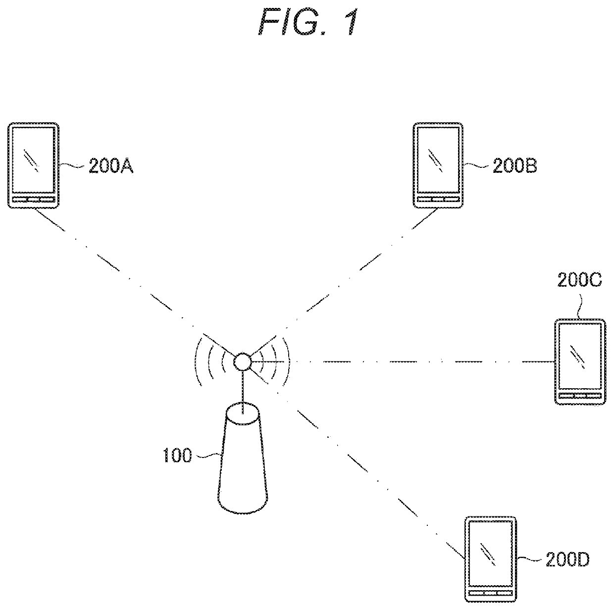
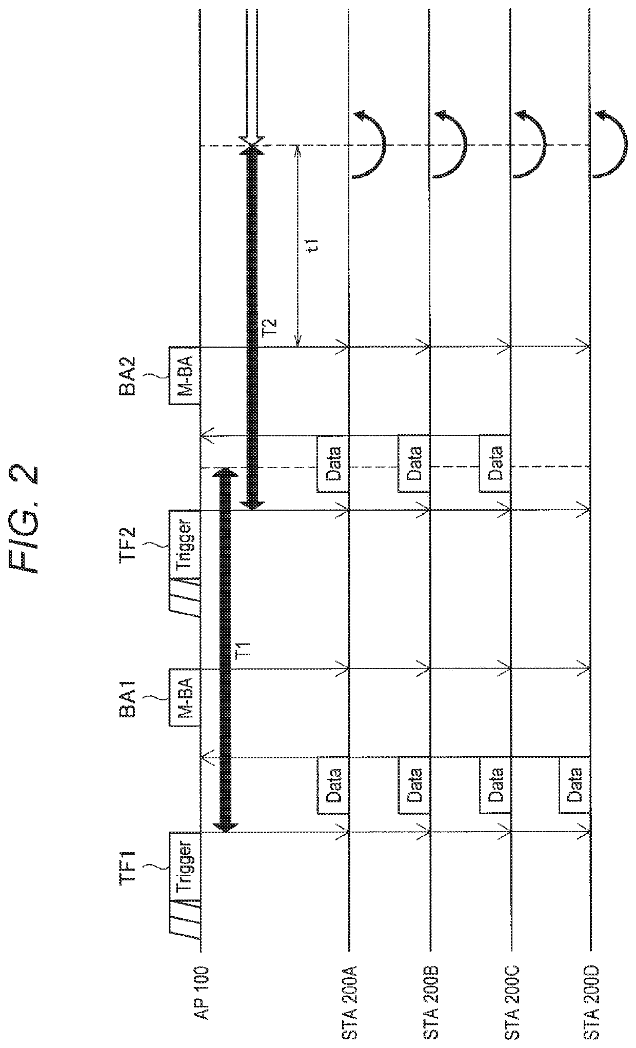
[0195]FIG. 21 is a diagram illustrating operation of the AP 100 and the STA 200 in a case where the AP 100 transmits different types of transition information to each of the STAs 200. In FIG. 21, the AP 100 transmits the trigger frame (TF1) to the STAs 200A to 200D, and then, the STAs 200A to 200D enter the centralized communication mode.
[0196]Here, the AP 100 transmits the trigger frame (TF1) containing the transition information to the region of the trigger frame ...
third embodiment
7. Third Embodiment
[0264]The above description is an example in which transition information is arranged in various frames to be transmitted. The following description is an example in which the STA 200 that has received the transition information determines whether or not to continue the centralized communication mode.
[0265]FIG. 32 is a diagram illustrating operation of the AP 100 and the STA 200 in a case where the STA 200 that has received the transition information determines whether or not to continue the centralized communication mode. Note that FIG. 32 illustrates an example in which the transition information is arranged in the region of the trigger frame that can be referred to by all of the STA 200.
[0266]In FIG. 32, the AP 100 transmits the trigger frame (TF1) to the STAB 200A to 200D, and then, the STAB 200A to 200D enter the centralized communication mode. In FIG. 32, after receiving the trigger frame (TF1), the STAB 200A to 200D set the length of the duration of the cen...
PUM
 Abstract
Description
Claims
Application Information