
Non-pneumatic surgical tourniquet

a surgical and non-pneumatic technology, applied in the field of non-pneumatic surgical tourniquets, can solve the problems of pneumatic system cuffs, pneumatic system cuffs can be quite costly, and the pneumatic system is expensive in large par

Active Publication Date: 2022-11-22
MAR MED INC
View PDF23 Cites 0 Cited by
  • Summary
  • Abstract
  • Description
  • Claims
  • Application Information

AI Technical Summary

Benefits of technology

The system provides a cost-effective, simple, and efficient method for restricting blood flow, reducing skin irritation and nerve injury, and is easy to apply, suitable for various body parts with minimal training, enhancing surgical precision and safety.

Problems solved by technology

Despite advantages of the pneumatic systems, such as providing accurate pressure monitoring, there are notable disadvantages to pneumatic tourniquets as well.
Primarily, pneumatic systems are costly in large part due to the need for equipment and instrumentation to provide and measure pressure.
But even the cuffs used in pneumatic systems can be quite costly.
Additionally, effective use of pneumatic systems can be somewhat demanding.
The equipment and tubes associated with pneumatic systems is obtrusive, and requires the technical knowledge and skill of often multiple operators from start to finish.
However, inflation can pinch or irritate skin and their high profile can be obstructive of the surgical site.
Moreover, pneumatic systems can be painful to wear and may cause nerve injury to the wearer.

Method used


Image

  • Non-pneumatic surgical tourniquet
  • Non-pneumatic surgical tourniquet
  • Non-pneumatic surgical tourniquet

Examples


Embodiment Construction

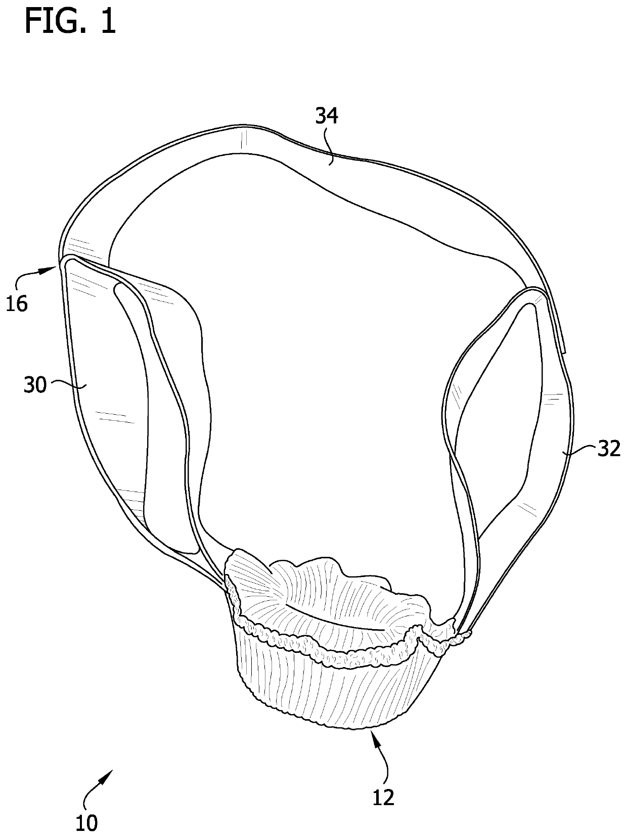
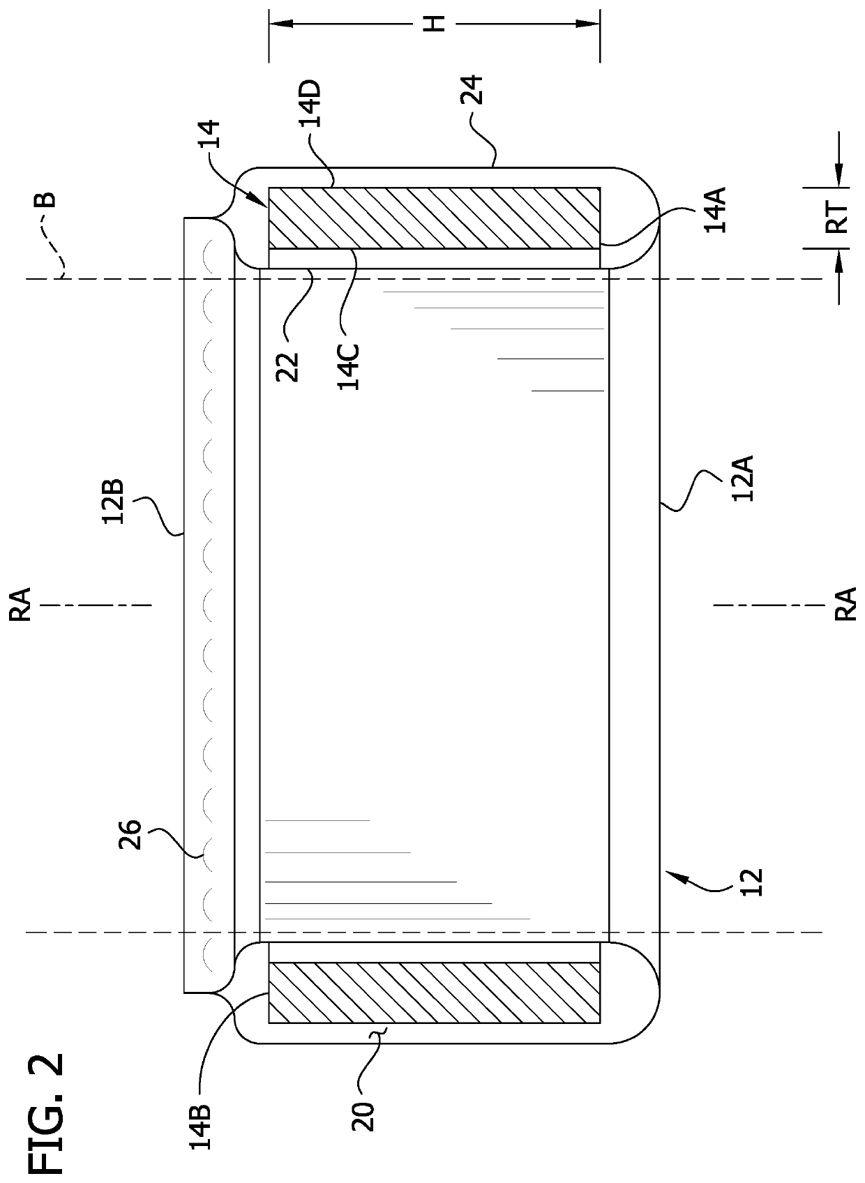
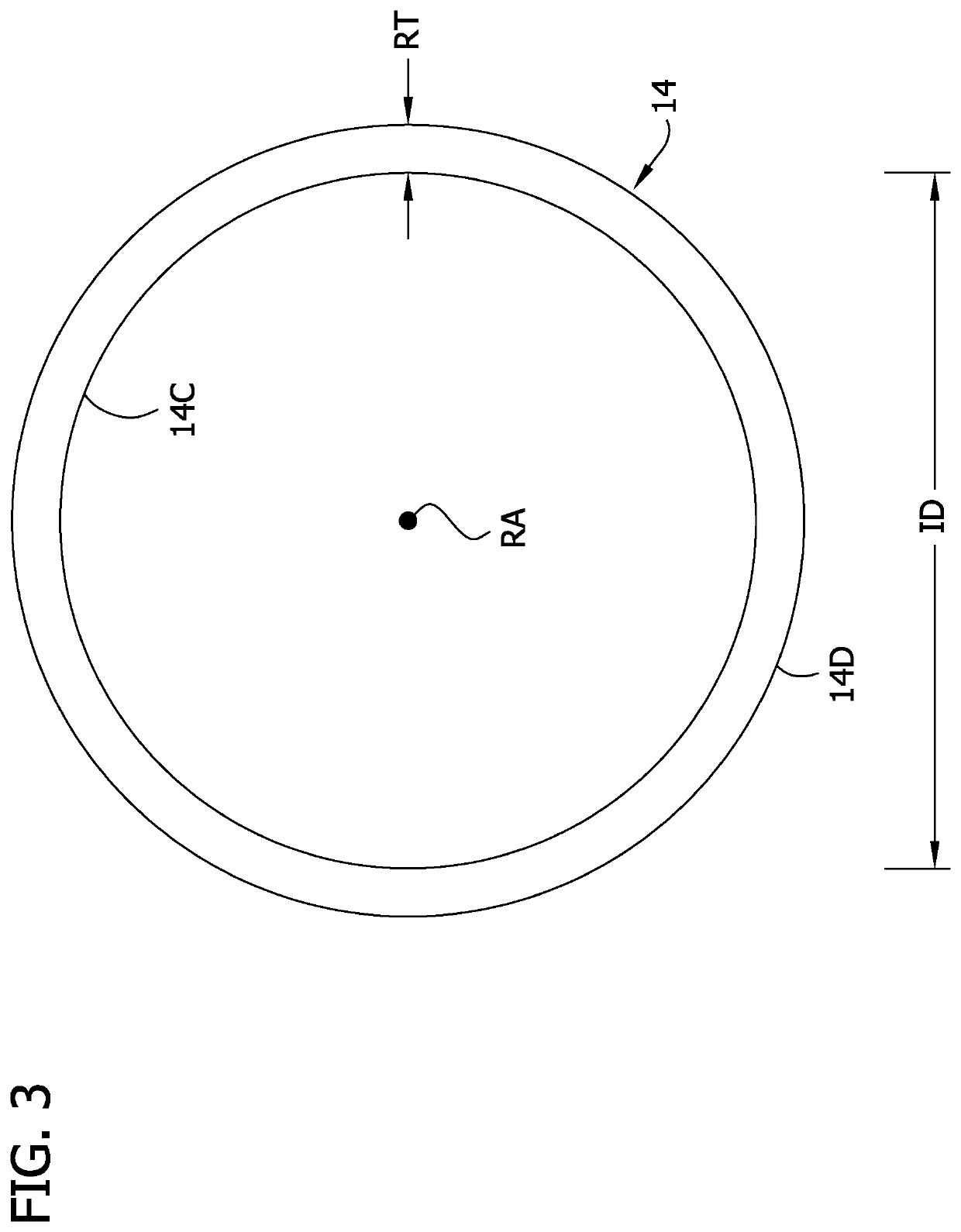
[0033]Referring to FIGS. 1 and 2, one embodiment of a non-pneumatic tourniquet is generally indicated at reference number 10. The tourniquet 10 includes an annular cover, generally indicated at 12, and an elastic compression ring, generally indicated at 14, which is received in the annular cover. A handle, generally indicated at 16, is attached to the cover 12 for pulling the tourniquet 10 onto a body part B of a subject (e.g., a human or animal surgical patient). Suitably, the tourniquet 10 is sized for a particular type of body part B (e.g., a portion of a limb) and may be configured to operatively restrict blood flow to any body part of that type within a normal size range (i.e., the tourniquet may be a one-size-fits-all device). In the illustrated embodiment, the tourniquet 10 is configured to operatively engage the arm of a patient to restrict blood flow to a distal portion of the arm. Other embodiments of tourniquets may be configured to operatively engage and restrict blood f...


PUM


Abstract

A non-pneumatic tourniquet including a tourniquet ring configured to resiliently constrict around a body part of a subject. The tourniquet ring defines a plurality of openings. A handle moves the tourniquet ring onto the body part and includes a first strap having a first end secured to the tourniquet ring at one of the openings and a second end secured to the tourniquet ring at one of the openings. A second strap has a first end secured to the tourniquet ring at one of the openings and a second end secured to the tourniquet ring at one of the openings.

Description

FIELD[0001]The present disclosure generally relates to non-pneumatic surgical tourniquets.BACKGROUND[0002]A tourniquet is a constricting or compressing device, used to control venous and arterial circulation to an extremity for a period of time. Tourniquets are commonly used in orthopedic surgical procedures and enable surgeons to work in a bloodless operative field by preventing blood flow to an extremity. With better visibility, tourniquets allow surgical procedures to be performed with improved precision, safety and speed.[0003]Tourniquets can be pneumatic (gas pressured constriction) or non-pneumatic (mechanical or elastic pressured constriction). But pneumatic tourniquets have become nearly standard in surgical procedures for a number of years. A pneumatic tourniquet system typically involves three components; an inflatable cuff, a compressed gas source, and an instrument that monitors and controls cuff pressure. In order to use a pneumatic tourniquet effectively, blood must fi...

Claims


Application Information

Patent Timeline
Patent Type & Authority Patents(United States)
IPC IPC(8): A61B17/132A61B90/00A61B17/00
CPCA61B17/1325A61B90/06A61B2017/0046A61B2017/00849A61B2017/00862A61B2017/00889A61B2090/061A61B17/1322A61B2017/0042
Inventor MAROGIL, JERRY PAUL
Owner MAR MED INC
Learn More