
Suspension control assembly and a kit of parts for

a control assembly and suspension technology, applied in resilient suspensions, interconnection systems, vehicle components, etc., can solve problems such as significant loss of traction, unsafe traction conditions, and overwhelm the amount of grip available, so as to reduce the possibility of the rear of the vehicle getting unstabl

Active Publication Date: 2022-11-22
BROWN KENNETH NORMAN
View PDF5 Cites 0 Cited by
  • Summary
  • Abstract
  • Description
  • Claims
  • Application Information

AI Technical Summary

Benefits of technology

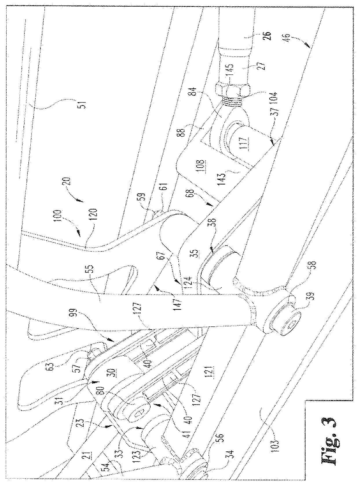
[0008]First (back) and second (front) extensions are radially spaced from each other and extend perpendicularly between the first and the second elongate members. The first extension also interconnects with the first elongate member adjacent the first (left) and the second (right) pivot member attachment orifices thereof. This posits the first and second extension midway along the first and second elongate members. The second extension is attached to the second elongate member and radially spaced from the first extension. The second extension includes third (left) and fourth (right) pivot member orifices at the far radial edge thereof. The pivot member orifices of the first and the second extensions are aligned with each other to insert the first and the second pivot members therethrough. The first and the second pivot members also extend through the pivot orifices of the straight and the symmetrical pivot links. Accordingly, when connected to the vehicle, the K-link control module is advantageously centered about the roll axis of the axle housing and attached to the frame. During high-speed cornering, this allows the K-Link control frame module or suspension control assembly to keep equal force on both rear wheels and to maintain control of the vehicle. Thus, the vehicle is much more stable during high-speed cornering and reducing the possibility of the rear of the vehicle getting unstable and out of control with the car possibly spinning around.
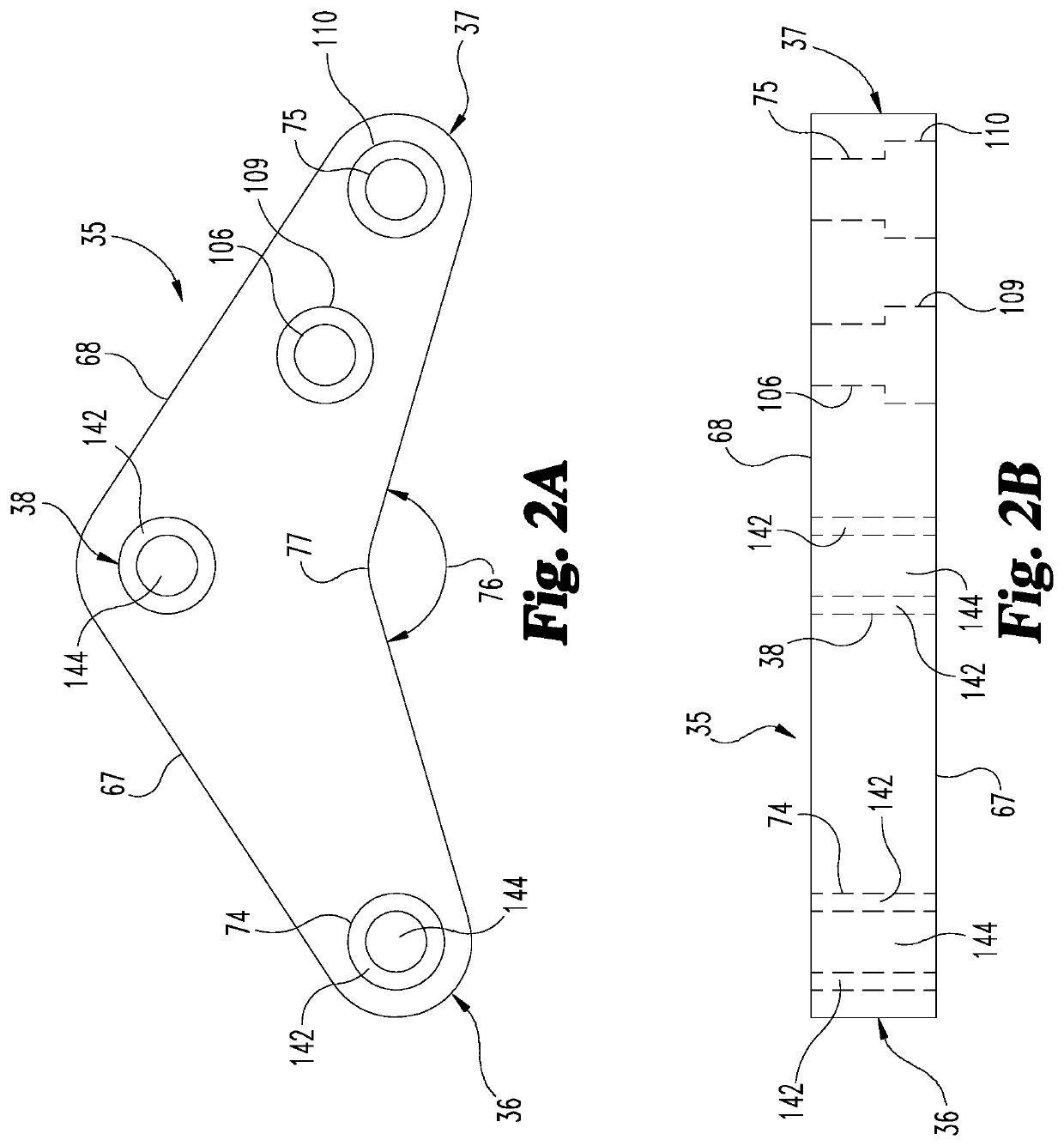
[0009]To help balance the forces on each rear wheel during high-speed cornering, the asymmetrical link includes first and second legs with an angle therebetween in the range of 95 degrees to 175 degrees, particularly in the range of 115 degrees to 160 degrees, and more particularly in the range of 155 degrees to 160 degrees. The length of the radius rods is adjustable to balance the weight on each wheel during high-speed cornering. The radius rods can be lengthened or shortened to adjust the rear roll center.

Problems solved by technology

In performance driving with live-axle or straight rear-axle suspensions, automobiles going around a corner at high speeds can create significant loss of traction.
As the body of the car rolls in cornering, the rear axle rolls as well and in performance driving creates a potentially unsafe traction condition.
As the weight on the rear outside tire increases, it can overwhelm the amount of grip available through the rear tire contact patch, producing what is referred to as a loose condition equating to the loss of control of the rear of the car.
Rear anti-sway bars help reduce the roll differential between the rear body components, but this can still lead to excessive weight transfer and loss of control.

Method used


Image

  • Suspension control assembly and a kit of parts for
  • Suspension control assembly and a kit of parts for
  • Suspension control assembly and a kit of parts for

Examples


Embodiment Construction

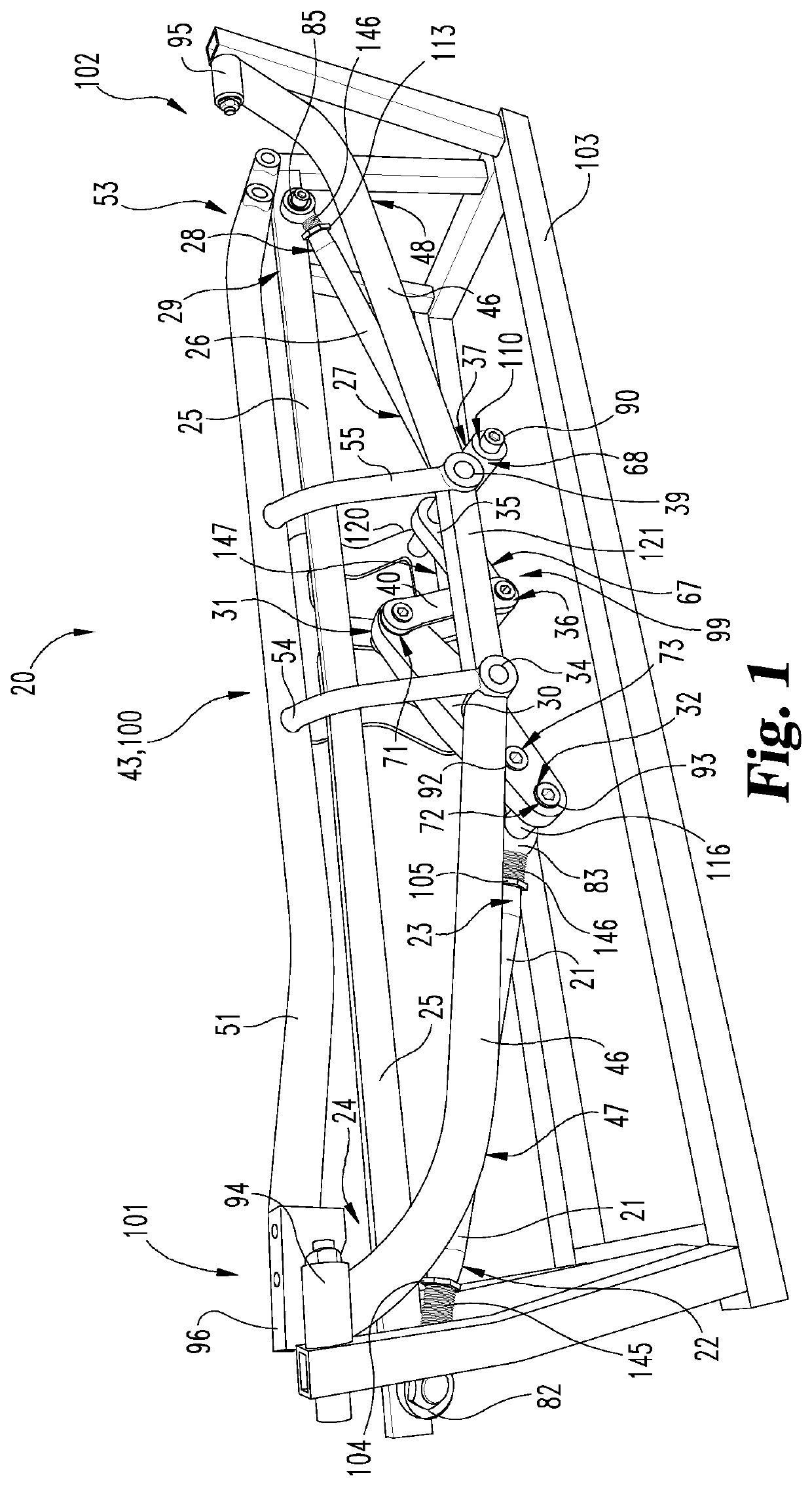
[0031]FIG. 1 is an illustrative elevated view picture or drawing of the present invention with the left side of suspension control assembly 20 extended forward and attached to display stand 103. In this illustrative embodiment, the suspension control assembly 20 includes a suspension control module 99 and a frame module 100 or a single unit frame 43 interconnected by a first or left-side 34 and a second or right-side 39 pivot fastener such as commercially available round Allen-head stripper bolts. When the suspension control module is connected to the opposite ends of a vehicle's straight axle housing, and the frame module 100 or frame 43 is connected to the opposite sides of the vehicle and a downward force is applied to one end of the straight axle housing, the other end of the axle housing is pushed down by the suspension control assembly to maintain the straight axle housing in a level position during cornering. Thus, both rear wheels maintain contact with and apply equal force ...


PUM


Abstract

Disclosed is a vehicular suspension control assembly and a kit of parts therefore configured to connect to opposite ends of a vehicle axle housing and to opposite sides of the vehicle. The assembly includes a control module configured to connect to the opposite ends of the vehicle axle housing and a frame module configured to connect to the opposite sides of the vehicle. The control and frame modules are interconnected with pivot control members to allow both modules to keep equal weight on the rear wheels during vehicle cornering. The control module has a straight pivot link connected to one side of the axle housing and an interconnected asymmetrical pivot link connected to the other side of the axle housing. When cornering, additional weight is applied to one side of the axle housing. In response, the pivot links of the control assembly transfer weight to the other side of the housing, to keep equal weight on the rear wheels.

Description

TECHNICAL FIELD[0001]This invention generally relates to vehicular suspensions and, particularly, to a control assembly and a kit of parts for a vehicular suspension that keeps both rear wheels on the ground during cornering.BACKGROUND OF THE INVENTION[0002]In performance driving with live-axle or straight rear-axle suspensions, automobiles going around a corner at high speeds can create significant loss of traction. As the body of the car rolls in cornering, the rear axle rolls as well and in performance driving creates a potentially unsafe traction condition.[0003]When driving in a straight line there is equal weight (force) on both rear tires. In high-speed cornering as the rear body / axle rolls going through the corner, the weight on the inside tire lessens and begins to lift off the road, which in turn reduces the tire contact patch to the road. As the weight on the rear outside tire increases, it can overwhelm the amount of grip available through the rear tire contact patch, pr...

Claims


Application Information

Patent Timeline
Patent Type & Authority Patents(United States)
IPC IPC(8): B60G21/05B60G21/00B60G5/04B60G7/00
CPCB60G21/05B60G5/043B60G7/001B60G21/005B60G2204/421
Inventor BROWN, KENNETH NORMAN
Owner BROWN KENNETH NORMAN
Learn More