Method of printing calibration pattern and printer

a technology which is applied in the field of printing calibration pattern and printer, can solve the problems of increasing the difficulty of regularly performing calibration in terms of cost and time efficiency, and the increase of the waste of recording paper

Inactive Publication Date: 2001-06-21
FUJIFILM CORP +1
View PDF0 Cites 37 Cited by
  • Summary
  • Abstract
  • Description
  • Claims
  • Application Information

AI Technical Summary

Problems solved by technology

However, since the conventional calibration method needs to select a calibration mode and make special and labor-consuming operations, or requires specific skills, it has been difficult to perfor...

Method used


Image

  • Method of printing calibration pattern and printer
  • Method of printing calibration pattern and printer
  • Method of printing calibration pattern and printer

Examples


Embodiment Construction

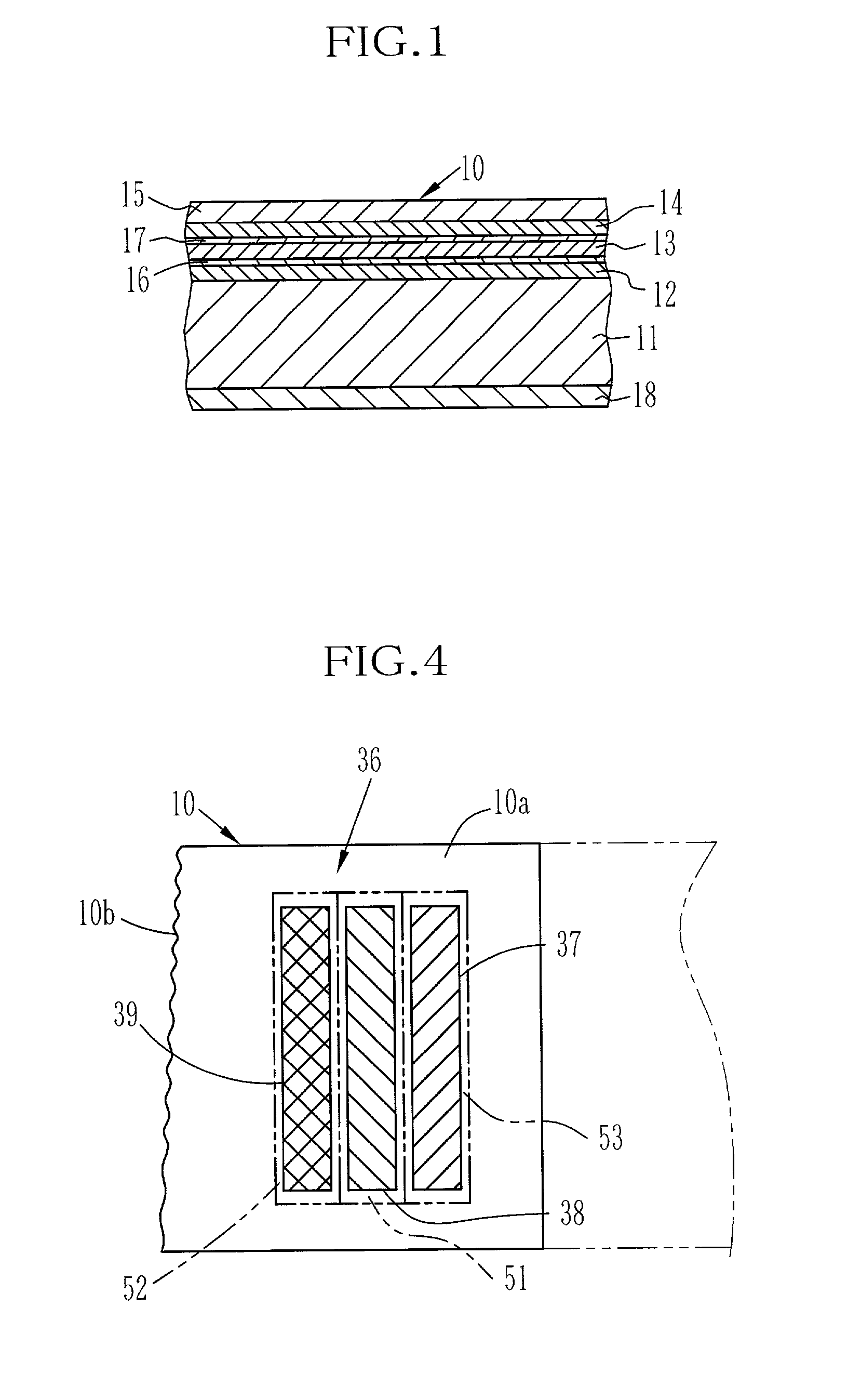
[0033] As shown in FIG. 1, a thermosensitive recording paper 10, hereinafter simply called the recording paper 10, has a thermosensitive cyan coloring layer 12, a thermosensitive magenta coloring layer 13, and a thermosensitive yellow coloring layer 14 formed atop another on one side of a base material 11. A transparent protective layer 15 is formed on an obverse of the recording paper 10, for protecting the coloring layers 12 to 14 from scratches or stains. The protective layer 15 is made from a transparent heat resistant resin material containing PVA (poly-vinyl-alcohol) as the main component. The three coloring layers 12 to 14 have different heat-sensitivities from each other that decrease with the depth or distance of the respective layers from the obverse of the recording layer 10. Intermediate layers 16 and 17 are formed between these three coloring layers 12 to 14, for adjusting the heat-sensitivities of the respective coloring layers 12 to 14. A back protective layer 18 is f...


PUM


Abstract

A printer prints a calibration pattern on a leading end portion of a roll of recording paper when the recording paper is loaded in the printer. A cutter cuts the leading end portion off the recording sheet so as to make an end edge rectangular to side edges of the recording sheet. A photometric device measures densities of the printed calibration pattern, and a system controller derives correction values for correcting density or color from the measured densities. After the calibration process, an image is printed in an image recording area on the recording paper following the leading end portion. For a printer that prints an image on a cut sheet recording paper, a calibration pattern is printed on a margin outside an image recording area. After densities of the calibration pattern are measured, the margin with the calibration pattern is cut off the recording paper.

Description

[0001] 1. Field of the Invention[0002] The present invention relates to a method of printing a calibration pattern for use in calibrating a printer, and also to a printer having a function to print a calibration pattern.[0003] 2. Background Arts[0004] In a thermosensitive color printer, thermosensitive color recording paper, hereinafter called simply the recording paper, is directly headed by a thermal head. The recording paper has thermosensitive coloring layers formed atop another, for developing a different color from each other. The coloring layers have different heat-sensitivities from each other that decrease with the depth or distance of the respective layers from an obverse surface of the recording layer. Because of the difference in heat-sensitivity between the three coloring layers, it is possible to record three color frames sequentially from the most sensitive coloring layer to the least sensitive coloring layer by applying increasing amounts of heat energy (mJ / mm.sup.2)...

Claims


Application Information

Patent Timeline
IPC IPC(8): B41J2/32B41J11/70B41J29/46G03B27/73
CPCG03B27/73H04N1/6036
Inventor FUKUDA, HIROSHIEBATO, TAKASHI
Owner FUJIFILM CORP
Why Eureka
Try Eureka