Holographic projection screen for displaying a three-dimensional color images and optical display system using the holographic screen

a technology of color images and projection screens, applied in the field of projection holographic screens, can solve the problems of limited viewing zones, large optics, and limited size of holographic screens manufactured by the conventional setup

Inactive Publication Date: 2001-07-05
KULNRUD GROLL AB +1
View PDF0 Cites 86 Cited by
  • Summary
  • Abstract
  • Description
  • Claims
  • Application Information

AI Technical Summary

Benefits of technology

[0014] Yet another object of the present invention is to provide an optical display system which is capable of providing stereoscopic or multi-view images to a viewer even when his (her) eyes move from specified position of a viewing zone.
[0015] Yet another object of the present invention is to provide an optical display system allowing the viewing zone of the holographic screen to extend in the vertical direction.

Problems solved by technology

However, as this type of holographic screen has a high angular and spectral selectivity, only a monochromatic image with a limited viewing zone can be displayed on the screen.
The most serious drawback of the described setup is necessity to use big size optics for the screen recording: at least one lens should be bigger than screen itself.
Therefore, the holographic screen manufactured by the conventional setup has the limited size, and producing big size screens is very cumbersome problem.
Also, in the conventional setup, when the viewer moves his (her) eyes from the viewing zone, the viewer can not watch 3D images.

Method used


Image

  • Holographic projection screen for displaying a three-dimensional color images and optical display system using the holographic screen
  • Holographic projection screen for displaying a three-dimensional color images and optical display system using the holographic screen
  • Holographic projection screen for displaying a three-dimensional color images and optical display system using the holographic screen

Examples


Embodiment Construction

[0030] The present invention will be described in detail by way of a preferred embodiment with reference to accompanying drawings, in which like reference numerals are used to identify the same or similar parts.

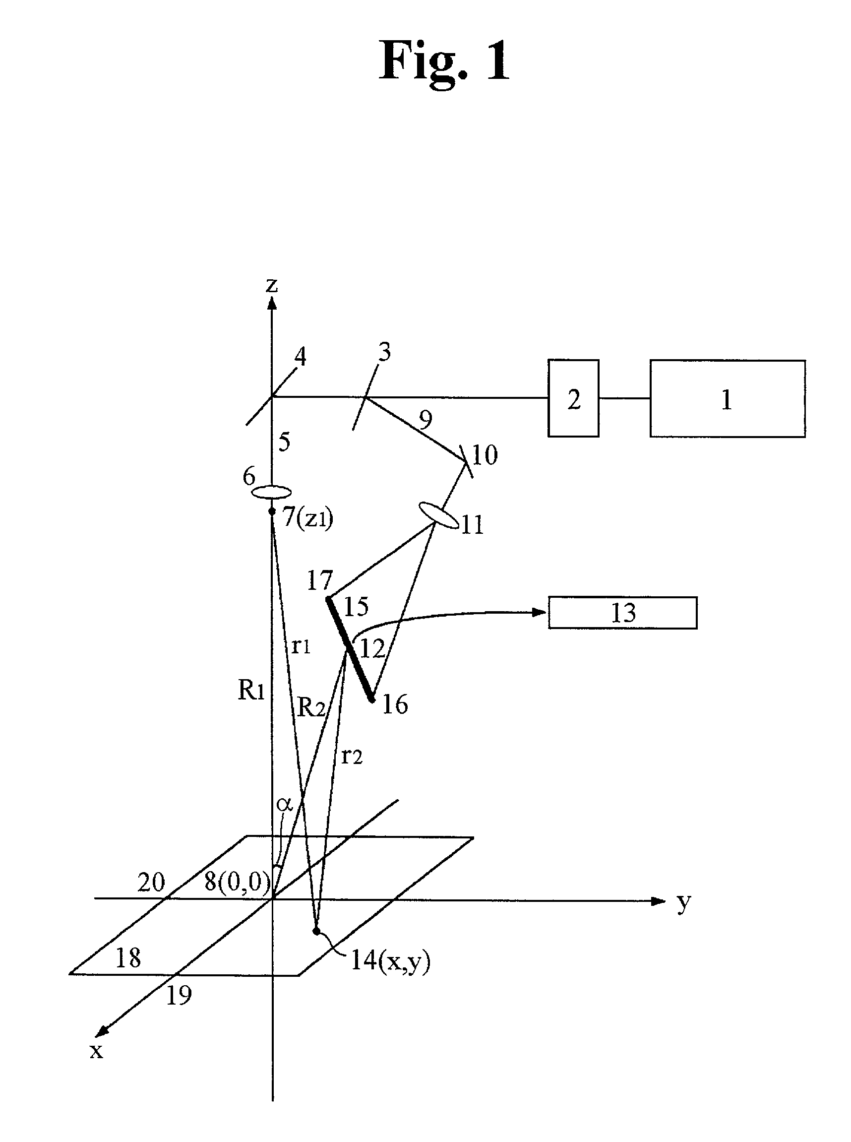
[0031] As shown on FIG. 1, a light beam from laser 1 after shutter 2 is divided into two beams by the beam-splitter 3. One of the obtained beams, namely reference beam 5 is reflected from the mirror 4 and focused by the lens 6 to the point 7 on the z-axis with coordinate z.sub.1 to form a diverging reference beam for the holographic screen recording on the photoplate 18. Usage of the diverging reference beam, unlike the previous art, makes it possible to use small size optics for the screen recording. The photoplate is disposed in the xy-plane and centered to the coordinate system origin 8. Second beam after beamsplitter 3, namely object beam 9, after reflection from mirror 10 is formed by the lens 11 so as to illuminate the diffuser 12 (the slit-shaped diffuser made of groun...


PUM


Abstract

A method is proposed, how to produce a holographic screen for projection of the three-dimensional color images, where a narrow and elongate slit-shaped diffuser is recorded on a hologram as an object to ensure the well defined viewing zone forming in the course of the image projection. Further to the back side of the holographic screen a mirror is attached to transform it into reflection mode of operation. Further, the holographic screen is rotated under a control of an eye-tracking system to provide viewing zone movement together with a viewer's eye. Also, a diffuser with vertical light scattering is attached to a surface of the holographic screen to increase a vertical size of a viewing zone of the holographic screen. In addition, two or more holographic screens manufactured by this method are combined in a mosaic manner to form a big size holographic screen.

Description

[0001] This application is a continuation-in-part of U.S. Ser. No. 09 / 432,410, filed on Nov. 2, 1999, which is a continuation-in-part of U.S. Ser. No. 08 / 897,052, filed on Jul. 18, 1997 and now abandoned.[0002] 1. Field of the Invention[0003] The invention relates generally to an application technique using holography, and more particularly, to a projection holographic screen for displaying a three-dimensional color images and an optical display system using the holographic screen.[0004] 2. Description of the Related Art[0005] A projection holographic screen is a kind of holographic optical element that serves as a general image display screen where an image, being projected on the screen, can be observed if an eye is disposed within a limited viewing zone. In order to observe a stereoscopic or multiview image, the viewing zones should be narrow enough to deliver to the left and right eyes of the viewer the left and right images correspondingly. For projection of the stereoscopic im...

Claims


Application Information

Patent Timeline
Patent Type & Authority Applications(United States)
IPC IPC(8): G02B5/32G03B21/60
CPCG02B5/32G03B21/606
Inventor SON, JUNG YOUNGBOBRINEV, VLADIMIR IVANOVICH
Owner KULNRUD GROLL AB
Why Eureka
Try Eureka