Dummy plug for wiring harness

a technology of wiring harnesses and plugs, which is applied in the direction of coupling device connections, securing/insulating coupling contact members, electrical apparatus, etc., can solve the problems of increasing cost, changing the basic structure of the mold, and increasing the complexity of the electrical system of motor vehicles of all types

Inactive Publication Date: 2001-07-12
QUALITY SYNTHETIC RUBBER INC
View PDF0 Cites 16 Cited by
  • Summary
  • Abstract
  • Description
  • Claims
  • Application Information

AI Technical Summary

Benefits of technology

[0016] Difficulties inherent in the related art are therefore overcome in a way that is simple and efficient while providing better and more advantageous results.
[0022] One advantage of the present invention is that the dummy plug is resistant to pressure blowouts, thereby making the invention functional in the market place.
[0023] Another advantage of the present invention is that the dummy plug is flush with the face of the connector, so that a pogo pin can detect whether or not the connector cavity is in use.

Problems solved by technology

The electrical systems of motor vehicles of all types are becoming increasingly complex.
However, such a change in specifications involves a change in the basic structure of the mold.
This creates an increase in cost because a completely different mold must be manufactured.
This increase in cost is often prohibitive.
However, it is difficult to detect it from the outside due to the fact that each of the dummy plugs is not inserted deeply inside the individual terminal accommodating cavities and are therefore not detectable.
The device as constructed above, is rather costly and requires precision machinery components.
However, the reliability of this type of detection is not sufficient due to the above difference of the locations of the individual inserted dummy plugs.
However, the current dummy plugs are made of rubber and are prone to pressure blowout.
However, the plastic plug used in Trummer does not extend to a latch arm of the connector.
Since the plug in Trummer does not extend to the latch arm of the connector, the dummy plug cannot be detected by a pogo pin.
However, in Endo, the same problem as in the Trummer patent exists.
The Micro Plastics dummy plug, while effective for its designed purpose, does not perform any sealing function.

Method used


Image

  • Dummy plug for wiring harness
  • Dummy plug for wiring harness
  • Dummy plug for wiring harness

Examples


Embodiment Construction

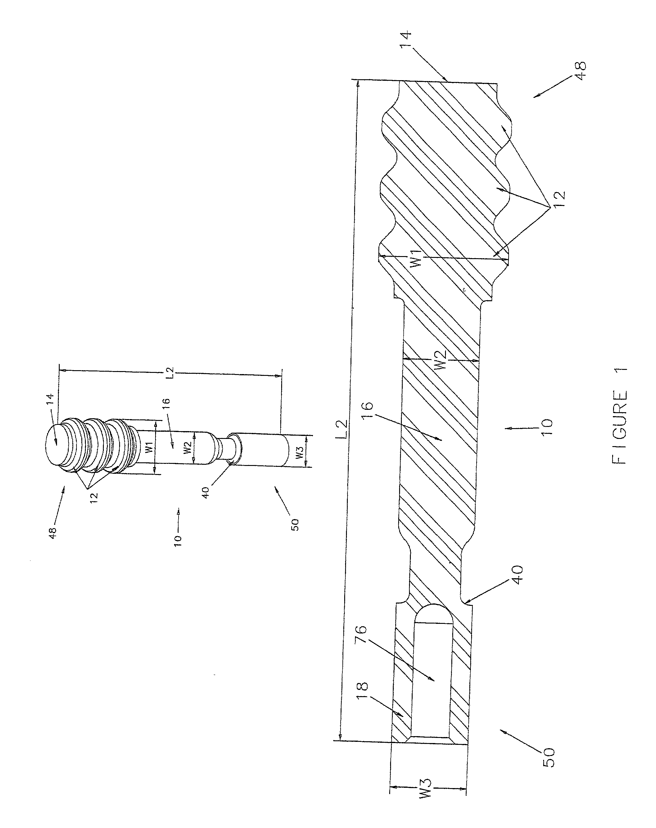
[0038] With respect to FIG. 1, an inventive dummy plug 10 is shown including a first end 48, a head 14, multiple ribs 12, a stem 16, a second end 50, a female end 18 with a base 40, a first width W.sub.1, a second width W.sub.2, a third width W.sub.3, and a second length L.sub.2. The female end 18 has an opening 76 for receiving male pins (not shown). The female dummy plug 10 can replace either male or female connectors (not shown). The first end 48, in this embodiment includes the head 14 and the multiple ribs 12. The second end 50 includes the female end 18 and the base 40. It is to be understood that the first and second ends 48, 50 can be of any shape or design as long as chosen using sound engineering judgment. In this embodiment, the dummy plug 10 is preferably made of 18 durometer, inherently lubricating silicon. The term "durometer" is a unit of hardness measurement. The dummy plug 10 can be made of harder material as well, and any other material chosen using sound engineeri...


PUM


Abstract

A dummy plug for wiring harnesses is disclosed. The dummy plug is used in an unused connector cavity of the wiring harness, thereby electrically isolating the connector cavity in the wiring harness to prevent short circuits. The dummy plug is substantially flush with the latch arm of the wiring harness, so that a pogo pin can determine whether or not the connector cavity is in use. The dummy plug has a design such that pressure blowout is prevented. A method for plugging an unused connector cavity is also disclosed, the method including the steps of providing a dummy plug having a head, a stem, and a female end, providing a wiring harness having at least one connector cavity and at least one latch arm and inserting the dummy plug into the unused connector cavity so that the female end is substantially flush with the latch arm.

Description

[0001] 1. Field of Invention[0002] This application is a continuation-in-part application of U.S. patent application Ser. No. 09 / 429,443, filed Oct. 28, 1999. This invention pertains to the art of wiring harnesses and connectors, and more particularly to dummy plugs used in unused connector cavities.[0003] 2. Description of the Related Art[0004] The electrical systems of motor vehicles of all types are becoming increasingly complex. Generally, motor vehicles are provided with one or more wiring harnesses, each of which is a prefabricated bundle of wires having appropriate terminals for interconnection of the appropriate electrical components and systems of the vehicle. Often, a wiring harness, or a portion thereof, must pass through a vehicle bulkhead, including firewalls, acoustical barriers or panels, pressure resistant walls and the like. It has been found most advantageous to utilize multiple terminal connectors to convey a number of electrical terminal connectors through such b...

Claims


Application Information

Patent Timeline
Patent Type & Authority Applications(United States)
IPC IPC(8): H01R13/443
CPCH01R13/443
Inventor HORNER, PATRICK L.
Owner QUALITY SYNTHETIC RUBBER INC
Why Eureka
Try Eureka