Valve arrangement

a valve arrangement and valve technology, applied in the direction of drinking water installation, gas/liquid distribution and storage, water supply installation, etc., can solve the problems of liquids and solid materials collecting in the crevices and interstices, and cannot be dealt with, so as to prevent corrosion damage or contamination of foodstuffs

Inactive Publication Date: 2001-07-26
FESTO AG & CO KG
View PDF0 Cites 10 Cited by
  • Summary
  • Abstract
  • Description
  • Claims
  • Application Information

AI Technical Summary

Benefits of technology

0012] On the other hand it may be an advantage, more particularly also to ensure protection against mechanical damage, for the casing body to be made as a dimensionally stable component. In any case it is an advantage for the control unit comprising a casing body and the valve unit accommodated therein, to constitute, as already mentioned, a common structural unit handled as such, which may be uniformly assembled and taken to pieces without entailing the taking to pieces of the individual components.
0013] To provide a sealing connection between the casing body and the valve unit a bonded or welded join may be provided. It is however more especially convenient to place a seal in between. Such seal is preferably molded on the control unit and preferably on the casing body, something which may be prov

Problems solved by technology

If such known valve arrangement is employed in the foodstuff and/or medical industry sector, particular problems arise as regards cleaning external surfaces of the valve arrangement.
For reasons of hygiene extreme cleanliness must be observed here, but difficulties however arise because liquids and also solid materials collecting in the crevice

Method used


Image

  • Valve arrangement
  • Valve arrangement
  • Valve arrangement

Examples


Embodiment Construction

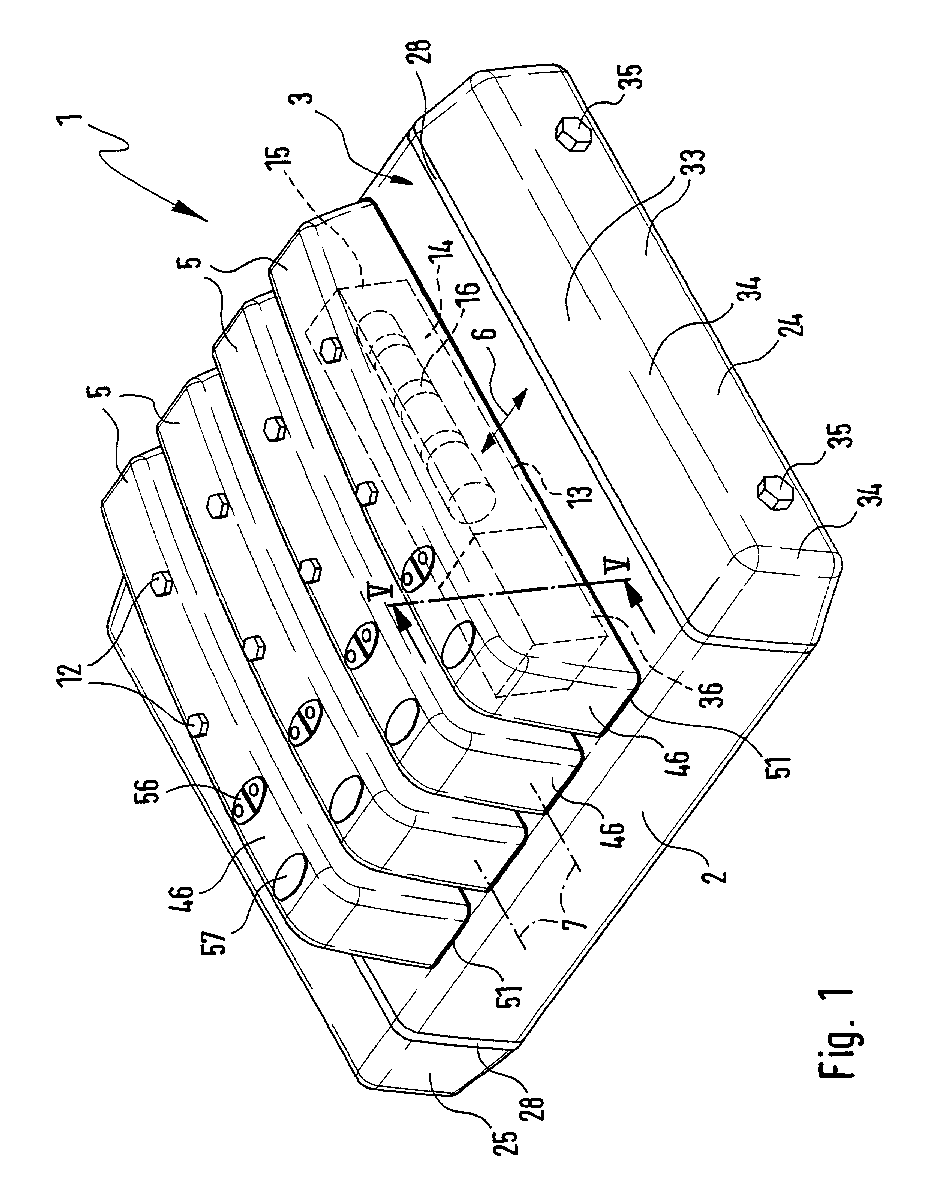
[0030] The valve arrangement of the working example generally referenced 1 comprises a plate-like valve carrier 2, which in the present case is made integral, but however could be modular and made up of a plurality of fixedly arranged valve carrier elements in a row.

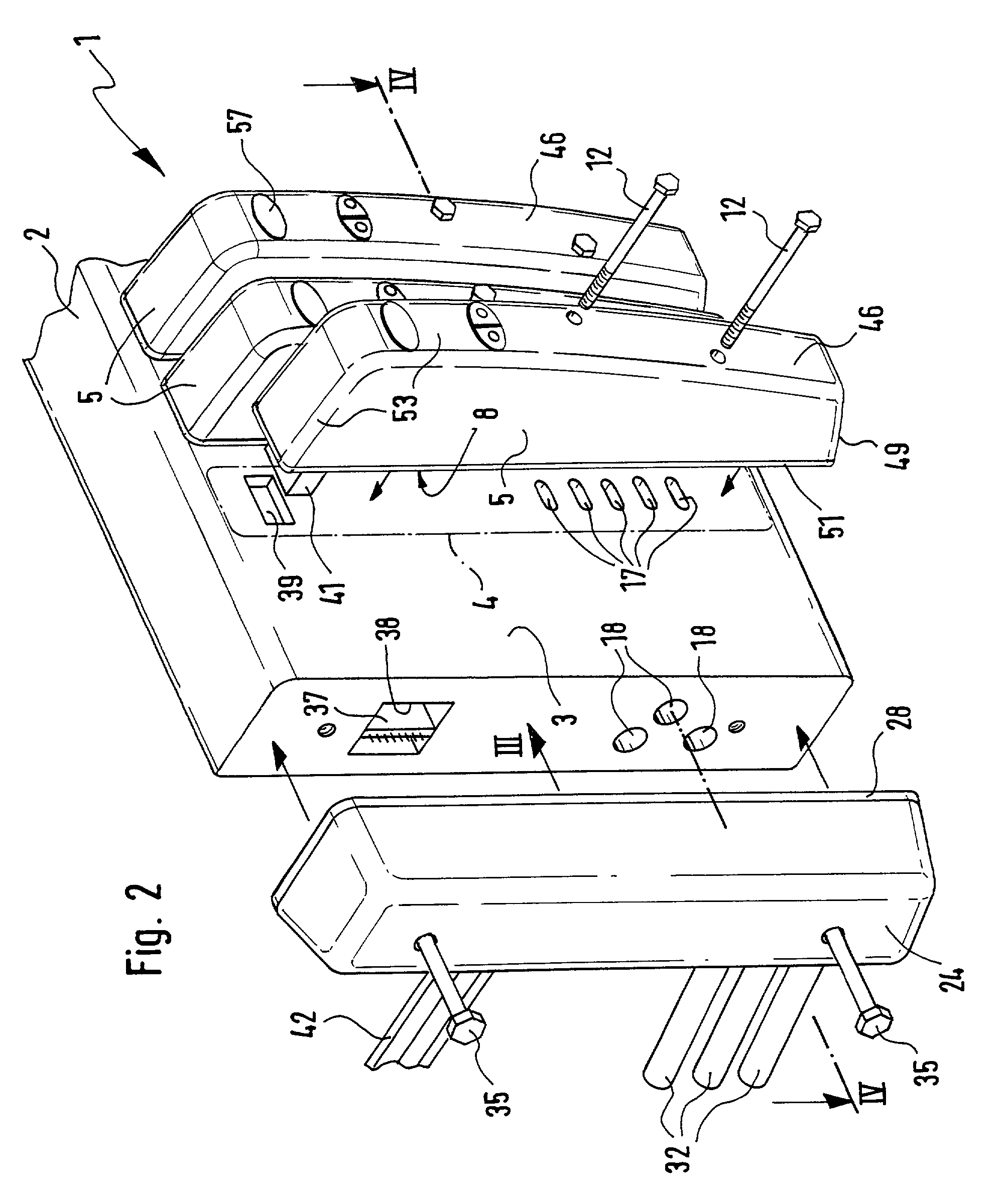
[0031] One of the two major faces of the valve carrier 2 constitutes a mounting side 3, on which a plurality of mounting areas 4 are provided, of which one is indicated in FIG. 2 in chained lines.

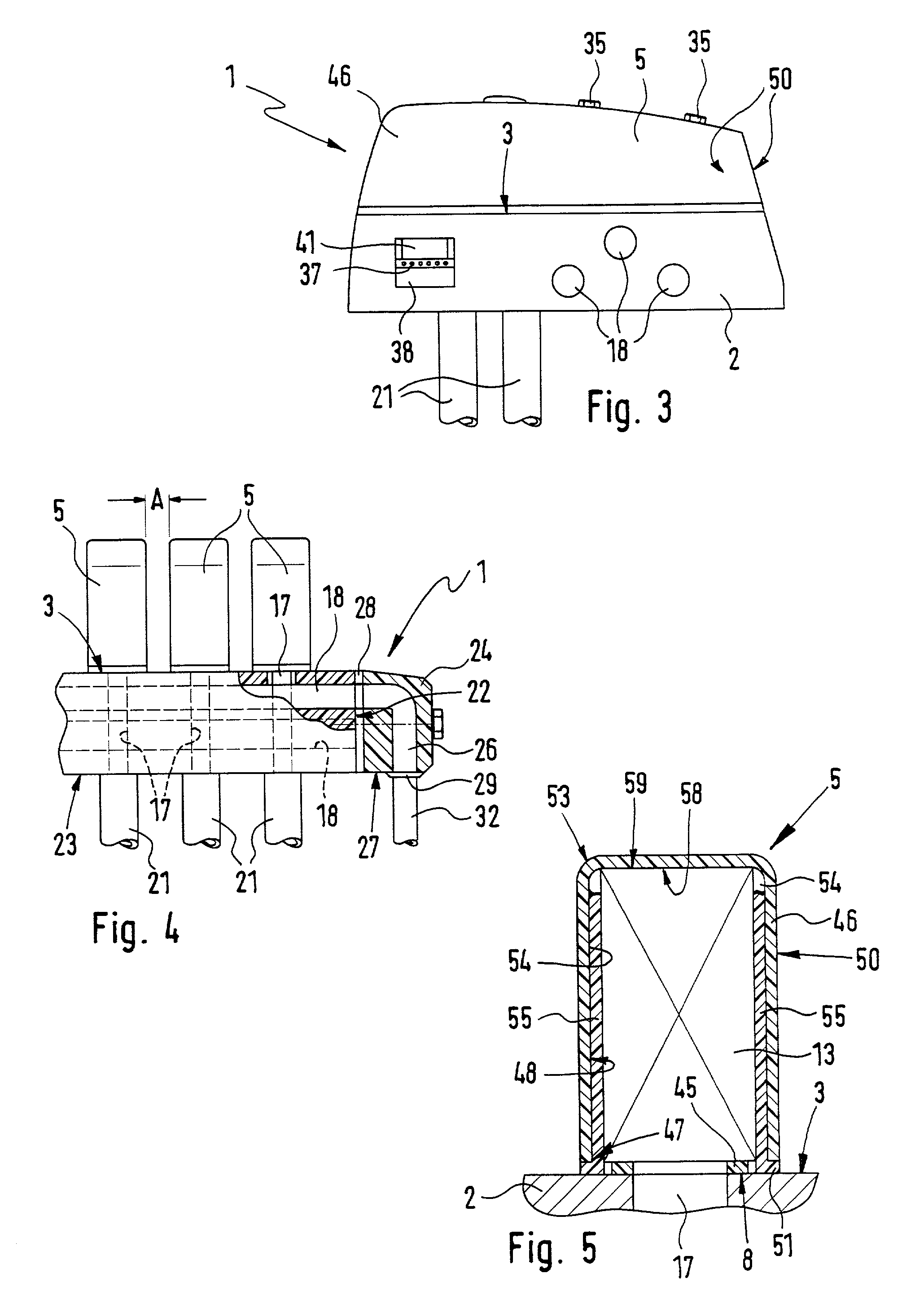
[0032] The valve carrier 2 is on its mounting side 3 provided with a plurality of valve control units 5. Same are arranged in a row one after the other, the direction 6 of the row, indicated by double arrow in FIG. 1 being at a right angle to the longitudinal axis 7 of the individual control units 5. The latter are consequently arranged alongside each other.

[0033] Each control unit 5 is preferably mounted detachably, its mounting side to the fore, on one of the mounting areas 4. Suitable attachment means 12, in the present case ...


PUM


Abstract

A valve comprising a valve carrier on which a plurality of control units are mounted adjacent to one another. Each control unit possesses a liquid-tight casing body in which the coomponent of a valve unit are received and is mounted on the valve carrier with a seal in between. It is in this manner that a liquid-tight, encapsulated and individual accommodation of the singular valve units is ensured.

Description

[0001] The invention relates to a valve arrangement comprising a valve carrier, on which a plurality of control units are mounted with a mounting side to the fore and alongside each other, such control units each having a valve unit with a valve communicating in a sealing manner with fluid ducts in the valve carrier and furthermore having at least one electrically operated valve drive serving for the actuation of the valve.THE PRIOR ART[0002] A valve arrangement of this type is disclosed for instance in the European patent publication 0 608 245 B1. This known valve arrangement is provided with a plate-like valve carrier, which on a component mounting side is provided bearing a plurality of adjacently placed control units. The control units are constituted by valve units, each respectively comprising a valve and an electrically operated valve drive. The valves communicate with fluids ducts extending in the valve carrier and are in the position of supplying connected loads with pressu...

Claims


Application Information

Patent Timeline
IPC IPC(8): F15B13/00F16K27/12F15B13/08F16K27/00
CPCF15B13/0814F15B13/0821F15B13/0828F15B13/0832F15B13/0853F15B13/0857F15B13/0875Y10T137/5283Y10T137/7062Y10T137/8376Y10T137/87885
Inventor NOTZ, FRANKMULLER, THOMAS
Owner FESTO AG & CO KG
Why Eureka
Try Eureka